background image

Rinnai Australia

29

Installation Manual

HEATER INSTALLATION

9.

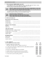
INSTALLATION AND COMMISSIONING CHECKLIST

Complete 

BOTH

 the “INSTALLATION RECORD” (Step 10.) and “FINAL CHECKLIST” (Step 11.) below.

Instruct customer on functions and operation of the heater and remote control.

Ensure the customer understands the content of this manual.

10. INSTALLATION RECORD 

INSTALLERS / GAS FITTERS DETAILS

Installers Name:

_____________________________________________________________________

Company Name:

_____________________________________________________________________

Company Address:

_____________________________________________________________________

COMPANY CONTACT DETAILS

Telephone:

_____________________________________________________________________

Mobile Phone:

_____________________________________________________________________

COMPLIANCE DETAILS

Certificate of Compliance / Certification Number:

 ______________________________________________

Authorised Persons - Licence Number:

 _______________________________________________________

Installers Signature:

_____________________________________________________________________

Installation Date:

_____________________________________________________________________

APPLIANCE DETAILS

Model Number:

_____________________________________________________________________

Serial Number:

_____________________________________________________________________

Installation Address:

_____________________________________________________________________

_____________________________________________________________________

11. FINAL CHECKLIST

Advise the customer that during the initial burning period of approximately 2 hours, some
smoke and smell may be experienced. During this period the heater should be operated on
‘High’ and the space being heated should be well ventilated. 

For protection of young children or the infirm a secondary guard is required.

Ensure this Operation and Installation manual is left with the customer.

Ensure the Customer understands that:
No part of this appliance should be permanently removed.
Paper or other material must not be burnt in this appliance.
Young children and the infirm should be supervised at all times.

(To be completed by certified Gas Installer)

NO

/

YES

1. Appliance positioned in a suitable location

(clearances, combustible clearances, mantels & surrounds, etc.).

2. Is a Rinnai approved flue system installed & tested in accordance with the instructions?

3. Gas pressure checked and set?

4. Has the burner media been installed as per instructions?

5. Appliance tested for correct operation and to ensure no gas leaks?

6. Customer instructed on operating procedure and safety requirements

7. Is the end-user fully aware of operating procedure?

NOTE

WARNING

Summary of Contents for RHFE-950ETR

Page 1: ...Codes including local OH S requirements This appliance must be installed maintained and removed by an Authorised Person For continued safety of this appliance it must be installed and maintained in accordance with the manufacturers instructions All Rinnai gas products are A G A certified OPERATION INSTALLATION MANUAL Power Flued Flamefire Gas Space Heater RHFE 950ETR ...

Page 2: ...FE 950ETR Flamefire We trust you will have many years of comfort and enjoyment from your appliance BEFORE PROCEEDING WITH THE OPERATION OR INSTALLATION OF YOUR NEW HEATER PLEASE READ THIS MANUAL THOROUGHLY AND GAIN A FULL UNDERSTANDING OF THE REQUIREMENTS FEATURES AND OPERATION OF YOUR NEW APPLIANCE ...

Page 3: ...RATION WITHOUT THE REMOTE CONTROL AUTOMATIC MODE 10 OPERATION WITH THE REMOTE CONTROL 10 TURNING ON THE POWER 11 USING THE REMOTE CONTROL TO OPERATE THE HEATER 11 FLAME FUNCTION 12 PROGRAMMED HEATER OPERATION 13 PROGRAMMING THE CLOCK AND TIMERS 13 USING THE TIMERS 13 PRE HEAT 14 USING THE OVERRIDE FUNCTION 14 USING THE EXTRA LOW FUNCTION 14 THE LOCK FUNCTION 14 CARE AND MAINTENANCE 15 CLEANING 15 ...

Page 4: ...ENTS ITEM CHECKLIST The components for RHFE 950ETR heater are supplied in 3 separate cartons the following tables list which components are in each carton Ensure that the components listed are present before proceeding with the installation Component Descriptions Carton Contents Engine Fascia Burn Media Rinnai RHFE 950ETR Engine Remote Control 1 5V AAA Batteries x2 Remote Control Mounting Bracket ...

Page 5: ...5 ROOM AIR RETURN INLET FILTERS Dust filter meshing is fixed to the inlets of the room air return 3 ON OFF BUTTON Turns the heater On or Off 7 RECEIVER WINDOW BLOCKAGE INDICATOR Remote control receiver Indicator for filter louvre blockages 6 TIMER INDICATOR Indicates timer program status 9 BURNER MEDIA 4 CONTROL PANEL 10 OPERATION INDICATOR Indicates operation status 8 6 2 4 6 2 1 1 4 3 3 5 5 10 7...

Page 6: ...tting it wet FRONT REAR BATTERY COMPARTMENT COVER STANDBY ON Flame Lock Timer 2 Timer 1 Override Time Set Temperature Lock Clock AM PM Timer 1 Set Set ON OFF ON OFF Timer 2 Set Override ExtraLow Time Flame CONTROL BUTTONS Used to select the temperature flame picture and adjust timers 20 11 STANDBY ON BUTTON Stops and Operates the heater remotely FLAME BUTTON Sets the flame picture TIME SET BUTTON ...

Page 7: ...tions The Dual Timer feature means that you can Set and Forget your heater It will turn itself ON or to STANDBY at the times you have programmed until you cancel the Timer program Pre Heat This function automatically operates the appliance before the programmed ON time of the Timer in order to heat a room to the pre set temperature by the programmed ON time Remote Control Full function cordless re...

Page 8: ...d restraining d Heat emanating from the front of this appliance may over time affect the appearance of some materials used for flooring such as carpet vinyl cork or timber This effect may be amplified if the air in the room contains cooking vapours or cigarette smoke To avoid this possibility it is recommended that a mat be placed in front of the appliance extending at least 750 mm in front of it ...

Page 9: ...rm air discharge louvres and glass must be avoided DO NOT allow young children or the infirm to sleep directly in front of the heater while in operation DO NOT allow anyone to sit on or lean against the appliance DO NOT unplug the heater while it is in operation or while the fans are still cycling Unplugging the heater will cause any timer operation to stop Timer programs are stored in the memory ...

Page 10: ...the On Off button on the left hand side of the heater Operation in this manner is known as automatic mode In automatic mode the default set temperature is 22 C For operation in other modes the remote control must be used For the remote control functions to be available the heater must be switched between standby and off using the remote control The remote control emits an Infra Red IR signal and m...

Page 11: ...tteries NEVER mix old and new batteries Remove batteries if the remote control is not going to be used for a long period This will help avoid damage from leaking batteries To replace batteries simply unscrew the battery compartment cover located on the back of the remote control anti clockwise When installing new batteries ensure that the correct polarity is observed the polarity is engraved into ...

Page 12: ...o show that the flame function is in operation 3 Use the Up and Down buttons to select the desired flame picture The number of bars illuminated correspond to the flame picture setting selected To return to automatic mode press the Flame button a second time Should the room temperature reach 40 C whilst the flame function is activated the heater will switch off automatically This is a safety featur...

Page 13: ...timers may need to be re programmed Prior to using timers ensure that the desired temperature has been set See ADJUSTING THE TEMPERATURE on page 11 1 One or both Timers can be used While the heater is in operation to start Timer 1 press the Timer 1 button To start Timer 2 press the Timer 2 button The display briefly shows the status of each Timer e g Timer 1 ON Timer 1 OFF If the current time is o...

Page 14: ...er continues to operate with the main burner on low to provide a flame picture with minimal heat output In some cases this may still cause the room to become warmer than desired Extra Low Function ON When the room temperature exceeds the preset temperature with the Extra Low function ON the burner will reduce to an extra low setting The burner will return to normal to maintain the set temperature ...

Page 15: ... before cleaning filters DO NOT continue to use the heater once this Indicator is flashing When an obstructive build up is detected the Blockage Indicator LED which is located above the Receiver Window will begin to flash RED to let you know that there is a problem Once the Indicator is flashing if no action is taken the heater will eventually shut down to avoid overheating and a fault code of 14 ...

Page 16: ...e thermostat operates This is the sound of the solenoid gas valves opening and closing to regulate the gas flow and is normal When the appliance is turned off Convection fan continues to run after turning off This is to remove residual heat from the heat exchanger and stops once the appliance cools Other points Steam is discharged from the flue terminal High efficiency appliances tend to discharge...

Page 17: ...with self diagnostic electronics that monitor the appliance during start up and operation Should a fault occur the heater will shut down the fault that has caused the shut down will be indicated by a pair of flashing digits in the Error Display window and a RED flashing Operation Indicator Refer to the table below for probable cause and the suggested remedy Code Probable Cause Suggested Remedy 00 ...

Page 18: ...EM TRANSITION CASTING 22 FLUE TERMINAL LOCATION 23 HEATER INSTALLATION 24 1 UNPACKING THE APPLIANCE 24 2 CONNECTING THE FLUE SYSTEM 24 3 SECURING THE ENGINE 25 4 CONNECTING THE APPLIANCE TO THE GAS SUPPLY 25 5 INSTALLING BURNER MEDIA 25 6 COMMISSIONING 28 7 INSTALLING THE OUTER FASCIA PANEL 28 8 INSTALLING THE DRESS GUARD INNER FASCIA PANEL 28 9 INSTALLATION AND COMMISSIONING CHECKLIST 29 10 INSTA...

Page 19: ... 1 2 BSP flare Guard Mesh Guard Flue System Fan assisted twin chamber coaxial flue system provides air for combustion to the appliance and allows expulsion of combustion products to atmosphere Results in room sealed appliance Convection Fan Double diameter 160mm x 180mm 3 speed Centrifugal Combustion system Multi port burners Burner Media Ceramic Logs or Ceramic Stones Ignition system Continuous s...

Page 20: ...position of any studs noggins or other components of the wall structure For all installations ONLY Rinnai ASP ES Flue components MUST BE used The Rinnai RHFE 950ETR MUST NOT be flued into natural draft flue system or via a chimney Consult the Rinnai Power Flued Flamefire Space Heater Co axial Flue System Installation Manual supplied with flue kits ASPDFK or ASPKIT03 for detailed flue installation ...

Page 21: ...upplied The power cord passes through the gap at the rear left of the appliance Rinnai recommend the heater be plugged into a 240V 10A earthed power point The power point must be a maximum of 1500 mm to the side of the heater it must not be above the heater Alternatively the appliance can be direct wired if the power supply is to be concealed Consult a qualified electrician if direct wiring is req...

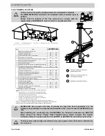
Page 22: ...minal Kit ASPKIT03 ESPIPE900 ESBEND ESWTKIT Order number of lengths as required Flue is NOT to be terminated under the floor or in a roof space Down Out and vertical through roof flue installations are permitted ONLY when the flue terminal is located externally For horizontal installations there must be a continuous fall of at least 2 to the termination point to drain condensate All terminations e...

Page 23: ...l or combustion air intake 500 300 Appliances up to 150 MJ h input 500 300 Appliances over 150 MJ h input up to 200 MJ h input 1500 300 Appliances over 200 MJ h input up to 250 MJ h input 1500 500 Appliances over 250 MJ h input 1500 1500 All fan assisted flue appliances in the direction of discharge 1500 k From a mechanical air inlet including a spa blower 1500 1000 Space heaters up to 50 MJ hr in...

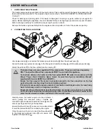
Page 24: ...ts MUST be used with this appliance Connections between the heater and the flue system MUST BE made in accordance with the Rinnai Power Flued Flamefire Space Heater Co axial Flue System Installation Manual supplied with flue kits ASPDFK or ASPKIT03 Ensure the flue spigot of the heater is properly secured to the flue connection on the flue system transition casting using the clip and clamp provided...

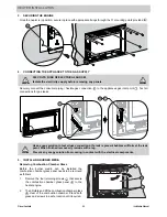
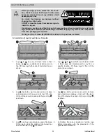
Page 25: ...as leaks Use a soapy solution to test all gas connections If a leak is present bubbles will form at the leak point When finished remove any residue with a rag Prevent any soapy solution from coming in contact with the electrical components Removing Combustion Chamber Glass Before the burner media can be installed the combustion chamber glass panel needs to be removed as follows 1 Remove the four r...

Page 26: ...s have a pair of pin holes in their bases log has an additional location pin on its top Fit these logs to the back of the burner box as shown 2 Logs have both a pin hole and a slot in their bases and dimensioned to only fit in a specific location Fit these logs to front of the burner box as shown 3 Log has both a pin hole and a slot in its base and a location pin at one end on its top Fit the log ...

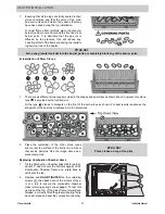
Page 27: ...pes and quantities as shown above however only stone type is provided with a location slot Fit the type stones to brackets on the front of the burner box as shown For best results randomise the alingment of these stone to achieve a more natural look 2 Place the remainder of the other stone types evenly over the surface of the burners in a manor that avoids patterns Use the image above as a placeme...

Page 28: ...the lower fascia mounting brackets of the heater engine 2 Position the fascia close to the heater engine and connect the RJ45 plug into the socket located on the inside top left of the fascia this connects the push button control panel via a communications cable to the heater engine s control box 3 Mount the outer fascia to the engine by hooking the inside fold of the top of the outer fascia to th...

Page 29: ...____________________________________________________ Serial Number _____________________________________________________________________ Installation Address _____________________________________________________________________ _____________________________________________________________________ 11 FINAL CHECKLIST Advise the customer that during the initial burning period of approximately 2 hours...

Page 30: ...30 240V bl bl r 3 2 1 3 2 1 4 3 2 1 9 8 7 6 5 4 3 2 1 r bk w gy or bl bl r w w bk bk 3 1 4 3 2 1 gr y 1 2 3 4 3 4 1 2 2 1 1 2 1 2 1 2 1 1 3 3 w bk r w bk r bl 1 1 4 4 w bk r bl COM HI MED LOW y r w bl MED LO COM HI bl br gr y F 3A OH TH 1 TF OH TH 2 R TH gy gy POV bl SP 8 6 3 4 1 pl gy or y or F R 3 bl w y bk F R 4 F R 2 Pilot bk br bl w bk bk bk y Wiring Diagram RHFE950ETR Issue A RCR SV1 PB SV3 ...

Page 31: ...Rinnai Australia 31 Installation Manual INSTALLATION NOTES ...

Page 32: ...nal Help Line Rinnai recommends that this appliance be serviced every 2 years Head Office 100 Atlantic Drive Keysborough VIC 3173 P O Box 460 Braeside Victoria 3195 Product Sales and Service National Phone 1300 555 545 Fax 1300 555 565 Technical Helpline and Spare Parts National Mon Fri 8am 5 30pm EST Phone 1300 555 545 Fax 1300 300 141 Cost of a local call higher from mobile or public phones E ma...

Reviews: