


- 21 -
Fig. 12
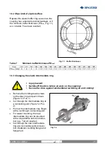
Fig. 11 Buffer thickness
10.2 Wear limit of elastic buffers
Replace the elastic buffer ring as soon as the
coupling has a distinct torsional backlash, or if
the minimum buffer thickness (PD
min
, Fig. 11)
acc. to table 7 has been reached.
Table 7
Minimum buffer thickness PD
min
:
Size
82
97 112 128 148 168 194 214 240 265 295 330 370 415 480 575
PD
min
[mm] 8
9
9
9
10
10
10
10
11
12
13
14
16
17
17
17
10.3 Changing the elastic intermediate ring
Injury hazard!
Switch-off the drive before all work on the coupling!
Secure the drive against unintentional switching on and rotating!
Remove the holding-down screws
on the claw ring and push it back
(Figure 12, Pos. 1)
Cut through the intermediate ring at
a connecting joint (Figure 12, Pos.
2)
Pull out the intermediate ring. Begin
at the cut through connecting joint.
For easier mounting, the new
intermediate ring can be provided
with a slip additive before introduc-
tion (e.g. Talcum powder).
Cut through the new intermediate
ring at a connecting joint and posi-
tion it between coupling flange and
flange hub.
RINGFEDER
®
TNM E
BAWN 002-GBR-2