


20068118
20
GB
Technical description of the burner
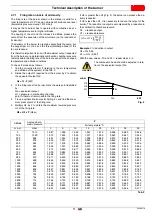
4.14 Servomotors (SQN13...)
Introduction
The servomotors that equip the burners of the
RS
range work di-
rectly on the air damper and the gas butterfly valve, without me-
chanical leverages but via the interposition of an elastic coupling.
They are commanded by the control box, which constantly
checks their position by means of a return signal from the optic
sensor inside the servomotor.
Important notes
All interventions (assembly and installation operations,
assistance, etc.) must be carried out by qualified personnel.
Before modifying the wiring in the servomotor connection
area, fully disconnect the burner control device from the
power supply (omnipolar separation)..
To avoid the risk of electrocution, protect the connection ter-
minals in a suitable manner and correctly fix the cover.
In the event of assembly, installation, maintenance, etc... it is
necessary to check that the wiring and the parameterisation
are in order.
Falls and collisions can negatively affect the safety func-
tions. In this case, the unit must not be operated, even if it
displays no evident damage.
Installation notes
Check the relevant national safety standards are respected.
The connection between the actuator command shaft and
the control element must be rigid, without any mechanical
play.
The tightening torque for the fixing screws should be 1.5 Nm.
It is recommended that this value is not exceeded to prevent
damaging the servomotor.
To avoid an excessive load on the bearings due to rigid
hubs, the use of compensation clutches without any
mechanical play is recommended (e.g. metal bellows-type
clutches).
It is advisable to oversize the drive shaft in relation to the
rated torque of the actuator.
The static torque is reduced when the electrical supply of the
actuator is switched off.
Arrange the H.V. ignition cables separately, as far as possi-
ble from the control box and the other cables.
Technical data
Tab. I
WARNING
To avoid accidents, material or environmental
damage, observe the following instructions!
Avoid opening, modifying or forcing the servo-
motor. The servomotor is equipped with a system
of optical feedback.
Power supply
AC / DC 24 V ± 20% (load inter-
face)
Safety class
EN 60730 part 1-14
Power absorption
Max. 7.5 W
Angle adjustment, usable
range
Max. 90°
Degree of protection
IP40
Work of field
0-90°
Opening time 0-90°
Min 5 sec.
Max 120 sec. depending on the
control box type
Direction of rotation
Anticlockwise
Torque operating
0.7 Nm
Torque off
0.4 Nm
Cable length
1.2 m
Radial load on the bearing
30 N
Axial load on the bearings
Max. 5 N
Weight
About 0.3 kg
Connecting cable
RAST2.5
Environmental conditions:
Operation
Climatic conditions
Mechanical conditions
Temperature range
Humidity
DIN EN 60721-3-3
Class 3K3
Class 3M3
-10 ... +60 °C
< 95% RH
WARNING
Condensation, formation of ice and the entrance
of water are not permitted!
Fig. 10
D8083
Summary of Contents for RS 25/E BLU Series
Page 2: ...Translation of the original instructions...
Page 65: ...63 20068118 GB Appendix Electrical panel layout RS 25 E BLU...
Page 66: ...20068118 64 GB Appendix Electrical panel layout RS 35 E BLU...
Page 67: ...65 20068118 GB Appendix Electrical panel layout RS 35 E BLU 3Ph...
Page 68: ...20068118 66 GB Appendix Electrical panel layout RS 25 35 E BLU...
Page 69: ...67 20068118 GB Appendix Electrical panel layout RS 35 E BLU 3Ph...
Page 70: ...20068118 68 GB Appendix Electrical panel layout...
Page 71: ...69 20068118 GB Appendix Electrical panel layout...
Page 72: ...20068118 70 GB Appendix Electrical panel layout...
Page 73: ...71 20068118 GB Appendix Electrical panel layout...
Page 75: ......


