


20152093
36
GB
Maintenance
Flame inspection window
Clean the glass of the flame inspection window (Fig. 40).
Boiler
Clean the boiler as indicated in its accompanying instructions in
order to maintain all the original combustion characteristics
intact, especially: the flue gas temperature and combustion
chamber pressure.
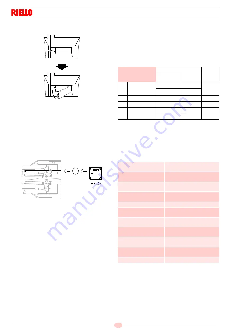
Flame presence check
Check the level of the flame detection signal with the “Check
mode” function from the flame control: the LEDs from 2 to 6
indicate the flame signal level, respectively. See “LED indicator
and special function” on page 38.
Check Mode
With burner flame on:
hold the reset button on the flame control pressed for at
least 3 sec.;
the button colour will change from green to yellow;
each operating status signalling LED will be compared to
20% of the maximum brightness;
press the reset button again (<0.5sec) to reset the standard
operation of the signalling LEDs.Boiler
Clean the boiler as indicated in its accompanying instructions in
order to maintain all the original combustion characteristics in-
tact, especially the flue gas temperature and combustion cham-
ber pressure.
Combustion
Carry out an analysis of the combustion flue gases.
Significant differences with respect to the previous
measurements indicate the points where most care should be
exercised during maintenance.
If the combustion values measured before starting maintenance
do not comply with applicable Standards or do not indicate
efficient combustion, consult the table below or contact our
Technical Support Service to implement the necessary
adjustments.
Tab. M
7.2.4
Safety components
The safety components must be replaced at the end of their life
cycle indicated in Tab. N. The specified life cycles do not refer to
the warranty terms indicated in the delivery or payment
conditions.
Tab. N
D709
Fig. 40
-
μ A
+
Fig. 41
20156526
EN 676
Air excess
CO
Max. output
1.2
Max. output
1.3
GAS
Theoretical max
CO
2
0 % O
2
CO
2
% Calibration
mg/kWh
= 1.2
= 1.3
G 20
11.7
9.7
9
100
G 25
11.5
9.5
8.8
100
G 30
14.0
11.6
10.7
100
G 31
13.7
11.4
10.5
100
Safety component
Life cycle
Flame control
10 years or 250,000
operation cycles
Flame sensor
10 years or 250,000
operation cycles
Gas valves (solenoid)
10 years or 250,000
operation cycles
Pressure switches
10 years or 250,000
operation cycles
Pressure adjuster
15 years
Servomotor (electronic
cam) (if present)
10 years or 250,000
operation cycles
Oil valve (solenoid)(if
present)
10 years or 250,000
operation cycles
Oil regulator (if present)
10 years or 250,000
operation cycles
Oil pipes/ couplings
(metallic) (if present)
10 years
Flexible hoses (if present)
5 years or 30,000 pressurised
cycles
Fan impeller
10 years or 500,000 start-ups
Summary of Contents for RS 200/M BLU
Page 2: ...Translation of the original instructions ...
Page 51: ...49 20152093 GB Appendix Electrical panel layout 0 ...
Page 55: ......


