20010309
32
GB
Maintenance
7.1
Notes on safety for the maintenance
The periodic maintenance is essential for the good operation,
safety, yield and duration of the burner.
It allows you to reduce consumption and polluting emissions and
to keep the product in a reliable state over time.
Before carrying out any maintenance, cleaning or checking oper-
ations:
7.2
Maintenance programme
7.2.1
Maintenance frequency
7.2.2
Safety test - with gas ball valve closed
It is fundamental to ensure the correct execution of the electrical
connections between the gas solenoid valves and the burner to
perform safely the commissioning.
For this purpose, after checking that the connections have been
carried out in accordance with the burner's electrical diagrams,
an ignition cycle with closed gas ball valve -dry test- must be per-
formed.
1
The manual ball gas valve must be closed
2
The electrical contacts of the burner limit switch need to be
closed
3
Ensures closed the contact of the low gas pressure switch
4
Make a trial for burner ignition
The start-up cycle must be as follows:
–
starting the fan for pre-ventilation
–
Performing the gas valve seal control, if provided
–
Completion of pre-ventilation
–
Arrival of the ignition point
–
Power supply of the ignition transformer
–
Electrical Supply of solenoid gas valves
Since the manual gas ball valve is closed, the burner will not light
up and its control box will go to a safety lockout condition.
The actual electrical supply of the solenoid gas valves can be ver-
ified by inserting a tester. Some valves are equipped with light
signals (or close/open position indicator) that turn on at the same
time as their power supply.
7.2.3
Checking and cleaning
Combustion
The optimum calibration of the burner requires an analysis of the
flue gases.
Significant differences with respect to the previous measure-
ments indicate the points where more care should be exercised
during maintenance.
Combustion head
Open the burner and make sure that all components of the
combustion head are in good condition, not deformed by the
high temperatures, free of impurities from the surroundings
and correctly positioned.
Burner
Clean the outside of the burner.
Clean and grease the cam variable profile.
Fan
Check to make sure that no dust has accumulated inside the fan
or on its blades, as this condition will cause a reduction in the air
flow rate and provoke polluting combustion.
Boiler
Clean the boiler as indicated in its accompanying instructions in
order to maintain all the original combustion characteristics in-
tact, especially the flue gas temperature and combustion cham-
ber pressure.
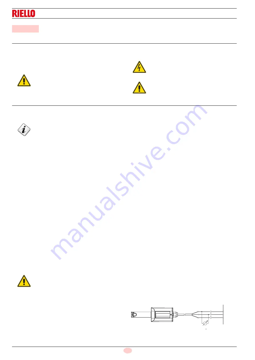
Power to flame sensor QRI
Min value for a good work: 3,5 Vdc (AZL display flame approx.
50%).
If the value is lower, it can depend on:
–
Flame sensor positioned incorrectly
–
Ow current (lower than 187 V)
–
Bad regulation of the burner.
To measure power, use a voltmeter with a 10 Vdc scale, connect-
ed as illustrated on the diagram.
7
Maintenance
DANGER
The maintenance interventions and the calibration
of the burner must only be carried out by qualified,
authorised personnel, in accordance with the con-
tents of this manual and in compliance with the
standards and regulations of current laws.
DANGER
Disconnect the electricity supply from the burner
by means of the main switch of the system;
DANGER
Close the fuel interception tap.
The gas combustion system should be checked at
least once a year by a representative of the man-
ufacturer or another specialised technician.
WARNING
IF THE ELECTRICAL SUPPLY OF THE GAS
VALVES OCCURS AT UNEXPECTED TIMES,
DO NOT OPEN MANUAL GAS BALL VALVE,
SWITCH OFF POWER LINE; CHECK THE
WIRES; CORRECT THE ERRORS AND RE-
PEAT THE COMPLETE TEST.
0...10 V
Ri > 10 M
:
X10-02 / 6
X10-02 / 4
X10-02 / 2
LMV...
+
D9174
Fig. 41
Summary of Contents for RLS 800/E MX
Page 2: ......
Page 77: ...39 20010309 Electrical panel layout Schéma tableau électrique ...
Page 78: ...20010309 40 Electrical panel layout Schéma tableau électrique ...
Page 80: ...20010309 42 Electrical panel layout Schéma tableau électrique ...
Page 81: ...43 20010309 Electrical panel layout Schéma tableau électrique 0 1 1 1 ...
Page 82: ...20010309 44 Electrical panel layout Schéma tableau électrique 0 ...
Page 89: ......
Page 90: ......


