


20067636
26
GB
Installation
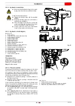
To calculate the required gas pressure at test point 1) (Fig. 28),
set the maximum modulating output required from the burner op-
eration:
-
find the nearest output value in Tab. H for the burner in ques-
tion.
-
read, on the right (column 1), the pressure at the test point 1)
(Fig. 28).
-
Add this value to the estimated pressure in combustion
chamber.
Example RLS 1600/EV C11 with natural gas G20:
Operation at maximum modulating output
Gas pressure at an output of 12400 kW
=
41 mbar
Pressure in combustion chamber
=
5 mbar
41 + 5
=
46 mbar
pressure required at test point 1)(Fig. 28).
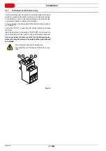
5.14.5 Pilot - gas train connection
The burner is fitted with a dedicated gas train that is fixed to the
pipe coupling.
It should be connected to the main train downstream the fil-
ter or the pressure adjuster (depending on configuration).
5.14.6 Ignition pilot burner
For proper operation, adjust gas pressure (measured at pressure
test point 1)(Fig. 29) as follows:
Tab. I
In the case of ignition problems check:
correct positioning of the ignition electrode;
the gas pressure, according to indications.
+
WARNING
Supply pressure 68 ÷ 500 mbar.
Model
Gas
mbar
Sm
3
/h
RLS 1600/EV C11
G20
26
19
RLS 2000/EV C11
G20
26
19
WARNING
Check pilot flame stability before starting up the
main burner.
1
Fig. 28
20124125
Fig. 29
20094558
Summary of Contents for RLS 1600/EV C11
Page 2: ...Original instructions ...
Page 48: ...20067636 46 GB Appendix Electrical panel layout 0 0 0 0 0 0 0 0 ...
Page 49: ...47 20067636 GB Appendix Electrical panel layout ...
Page 51: ...49 20067636 GB Appendix Electrical panel layout ...
Page 52: ...20067636 50 GB Appendix Electrical panel layout 0 1 1 1 ...
Page 53: ...51 20067636 GB Appendix Electrical panel layout 0 1 0 ...
Page 54: ...20067636 52 GB Appendix Electrical panel layout 0 1 1 1 2 1 3 1 1 1 1 1 1 1 41 4 4 1 1 2 1 ...
Page 55: ...53 20067636 GB Appendix Electrical panel layout 0 0 0 1 0 2 0 0 0 0 0 0 0 30 3 3 0 0 1 0 4 ...
Page 56: ...20067636 54 GB Appendix Electrical panel layout 0 0 1 2 0 0 3 3 3 0 1 4 ...
Page 62: ......
Page 63: ......