


20067636
16
GB
Technical description of the burner
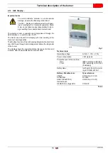
4.15 Servomotor (SQM48.4....)
Important notes
All interventions (assembly and installation operations,
assistance, etc.) must be carried out by qualified personnel.
Before modifying the wiring in the SQM4... system connec-
tion area, fully disconnect the burner control device from the
power supply (omnipolar separation).
To avoid the risk of electrocution, protect the connection ter-
minals in a suitable manner and correctly fix the cover.
Check the wiring is in order.
Falls and collisions can negatively affect the safety func-
tions. In this case, the unit must not be operated, even if it
displays no evident damage.
Assembly notes
•
Check the relevant national safety standards are respected.
•
The connection between the actuator command shaft and the
control element must be rigid, without any mechanical play.
•
To avoid an excessive load on the bearings due to rigid hubs,
the use of compensation clutches without any mechanical
play is recommended (e.g. metal bellows-type clutches).
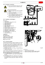
Installation notes
• Arrange the HV ignition cables separately, as far as possible
from the control box and the other cables.
• To avoid the risk of electrocution, make sure that the 230V AC
section of the SQM4... unit is fully separated from the function-
al low-voltage section.
• The static torque is reduced when the electrical supply of the
actuator is switched off.
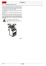
•
The housing cover may only be removed for short periods of
time for wiring or when making the addressing. In similar cas-
es, make sure that dust or dirt does not penetrate inside the
actuator.
•
The actuator comprises a PCB with ESD-sensitive compo-
nents.
•
The top side of the board carries a cover which affords pro-
tection against direct contact. This protective cover must not
be removed! The underside side of the board must not be
touched.
Technical data
Tab. G
WARNING
To avoid accidents, material or environmen-
tal damage, observe the following instruc-
tions!
Avoid opening, modifying or forcing the ac-
tuators.
WARNING
During the maintenance or replacement of the
actuators, be careful not to invert the connec-
tors.
Operating voltage
AC 2 x 12V via bus cable from the
base unit or via a separate trans-
former
Safety class
extra low-voltage with safe isolation
from mains voltage
Power absorption
26...34 VA
Protection level
to EN 60 529, IP 54, provided ade-
quate cable entries are used
Cable connection
RAST3,5 connectors
Rotation direction
- Anticlockwise (standard)
- Clockwise (inverted rotation)
Rated torque (max.)
20 Nm
Static torque (max.)
20 Nm
Operation time (min.)
for 90°
30 s.
Weight approx.
1.6
kg
Environmental conditions:
Operation
Climatic conditions
Mechanical conditions
Temperature range
Humidity
DIN EN 60 721-3-3
Class 3K3
Class 3M3
-20...+60°C
< 95% RH
Fig. 9
D8271
Summary of Contents for RLS 1600/EV C11
Page 2: ...Original instructions ...
Page 48: ...20067636 46 GB Appendix Electrical panel layout 0 0 0 0 0 0 0 0 ...
Page 49: ...47 20067636 GB Appendix Electrical panel layout ...
Page 51: ...49 20067636 GB Appendix Electrical panel layout ...
Page 52: ...20067636 50 GB Appendix Electrical panel layout 0 1 1 1 ...
Page 53: ...51 20067636 GB Appendix Electrical panel layout 0 1 0 ...
Page 54: ...20067636 52 GB Appendix Electrical panel layout 0 1 1 1 2 1 3 1 1 1 1 1 1 1 41 4 4 1 1 2 1 ...
Page 55: ...53 20067636 GB Appendix Electrical panel layout 0 0 0 1 0 2 0 0 0 0 0 0 0 30 3 3 0 0 1 0 4 ...
Page 56: ...20067636 54 GB Appendix Electrical panel layout 0 0 1 2 0 0 3 3 3 0 1 4 ...
Page 62: ......
Page 63: ......