


20067636
12
GB
Technical description of the burner
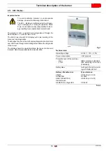
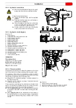
4.11
Electrical panel description
1
Supply cables, external connections and kits
2
Volt-free contacts output relay
3
Electronic cam transformer
4
Electronic control box
5
Ignition transformer
6
Shielding terminals
7
Emergency button
8
Fuel selector and enable signal to remote fuel selector
9
Light signalling of main fuel valve open
10 AZL display
11 Voltage present warning lamp
12 Light signalling of fan motor lockout and pump motor
13 Burner lockout warning lamp and reset switch
14 Heat request signal
15 Auxiliary transformer fuses
16 Auxiliary circuits fuse
17 Flame sensor plug/sensor socket
18 Main terminal supply board
19 Air pressure switch
20 Terminal board for O
2
kit
21 Plug/Oil valve socket/pump motor (derivation unit)
22 Plug/socket servomotor
23 Pump motor contactor and thermal relay
24 Off-automatic selector
25 Rpm sensor terminal board
NOTE
Two types of burner failure may occur:
Control box lockout:
the switching on of the button (
red
led
) 13)(Fig. 6) signals that the burner is in lockout. Release
by pressing button 13)(Fig. 6) or use the display.
Motor lockout
: release the pump motor by pressing the but-
ton on the relevant thermal relay.
see the inverter manual for the release of the fan motor.
4.12
Burner equipment
Gasket for gas train flange . . . . . . . . . . . . . . . . . . . . . . . . .No. 1
Gas flange fixing screws, M 16 x 50 . . . . . . . . . . . . . . . . .No. 8
Thermal insulation screen . . . . . . . . . . . . . . . . . . . . . . . . .No. 1
M 20 x 70 screws to secure
the burner to the boiler . . . . . . . . . . . . . . . . . . . . . . . . . . . No. 12
Pressure switch (for leak detection control) . . . . . . . . . . . .No. 1
Light oil flexible hoses . . . . . . . . . . . . . . . . . . . . . . . . . . . .No. 2
M20 nuts to secure the burner to the boiler door . . . . . . . No. 12
Instruction booklet . . . . . . . . . . . . . . . . . . . . . . . . . . . . . . No. 2
Spare parts list . . . . . . . . . . . . . . . . . . . . . . . . . . . . . . . . . .No. 1
1
8
13
10 11 14 9 12 1
2
3
5
6
7
24
4
6
21
23
20
19
18
22
17
25
2
16
15
20124430
Fig. 6
Summary of Contents for RLS 1600/EV C11
Page 2: ...Original instructions ...
Page 48: ...20067636 46 GB Appendix Electrical panel layout 0 0 0 0 0 0 0 0 ...
Page 49: ...47 20067636 GB Appendix Electrical panel layout ...
Page 51: ...49 20067636 GB Appendix Electrical panel layout ...
Page 52: ...20067636 50 GB Appendix Electrical panel layout 0 1 1 1 ...
Page 53: ...51 20067636 GB Appendix Electrical panel layout 0 1 0 ...
Page 54: ...20067636 52 GB Appendix Electrical panel layout 0 1 1 1 2 1 3 1 1 1 1 1 1 1 41 4 4 1 1 2 1 ...
Page 55: ...53 20067636 GB Appendix Electrical panel layout 0 0 0 1 0 2 0 0 0 0 0 0 0 30 3 3 0 0 1 0 4 ...
Page 56: ...20067636 54 GB Appendix Electrical panel layout 0 0 1 2 0 0 3 3 3 0 1 4 ...
Page 62: ......
Page 63: ......