


20026767
18
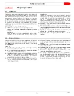
Installation
4.8
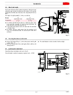
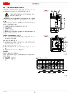
Combustion head adjustment
Installation operations are now at the stage where the blast tube
and sleeve are secured to the boiler as shown in Fig. 13.
It is now a very simple matter to set up the combustion head, as this
depends solely on the output developed by the burner at maximum
power.
It is therefore essential to establish this value before proceeding to
set up the combustion head.
There are three adjustments to make on the head:
•
outside air R1
•
central air R2
•
gas deliveries R3
In diagram (Fig. 14) find the notch to use for adjusting the air and
the gas, and then proceed as follows:
Outside air adjustment R1
Turn screw 4) until the notch identified is aligned with the front
surface 5) of the flange.
Gas adjustment R3
Loosen screws 1)(B) and 4)(B) and turn ring 2) until the notch
identified is aligned with index 3).
Central air adjustment R2
Turn choke 5) until the notch identified is aligned with screw
4).
Tighten the screws 1) and 4) fully down.
Example
Burner output = 1515 MBtu/hr.
If we consult diagram (Fig. 14) we find that for this output, the ad-
justments are:
•
outside air
R1 = 5.3
•
central air
R2 = 2.7
•
gas
R3 = 0.7
WARNING
The fan part of the burner shall be completely back-
ward using the guides.
6
4
(R1)
0
1
2
3
5
1
2
(R3)
4
3
5
(R2)
Fig. 13
AIR
GAS
D10450
Fig. 14
Burner max output
Notches (Air = Gas)
Summary of Contents for C9541400
Page 2: ......
Page 30: ...20026767 28 Appendix Spare parts A Appendix Spare parts...
Page 35: ......


