


20013962
16
GB
Electrical system
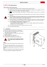
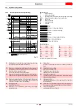
7.2
Electrical connections
C
– Capacitor
E
– Electrode
F
– Photoresistance
h1
– Hour counter
K
– Thermostat enabling start-up after preheating
MV
– Motor
PH
– Oil heater
RS
– Remote reset
SER
– Safety lockout device
S3
– Lock-out signal
T6A
– Fuse
TB
– Burner-earth
TL
– Limit thermostat
TS
– Safety thermostat
V1
– Oil valve
V2
– Safety lockout device
X7
– 7 pin plug
XP7
– 7 pole socket
7.2.1
Testing
Check the burner has stopped by opening the thermostats.
Make sure the operating burner locks out by covering the
photoresistance.
TO BE DONE BY
THE INSTALLER
CARRIED-OUT
IN FACTORY
Fig. 14
230V ~ 50Hz
CON
T
ROL BOX
MO550
D7240
Main switch
Black
Blue
Brown
Black
White
Blue
WARNING
The section of the conductors must be at least
1mm
2
. (Unless requested otherwise by local stan-
dards and legislation)
Summary of Contents for BGK3
Page 2: ......
Page 30: ......
Page 58: ...20013962 Notes Notas...
Page 59: ...20013962 Notes Notas...


