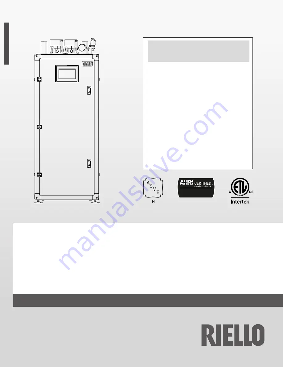
background image

co

d

. 2

0

18

32

4

8  r

e

v.

 2

0

4/

202

1

WARNING

:  If the information in this manual is not 

followed exactly, a fire or explosion may result causing 
property damage, personal injury or loss of life.

Do not store or use gasoline or other flammable 
vapors and liquids or other combustible materials in 
the vicinity of this or any other appliance. To do so 
may result in an explosion or fire.

What to do if you smell gas:
- Do not try to light any appliance;
- Do not touch any electrical switch; do not use any 

phone in your building;

- Immediately call your gas supplier from a neighbor’s 

phone. Follow the gas supplier’s instructions;

- If you cannot reach your gas supplier, call the fire 

department.

Installation and service must be performed by a 
qualified installer, service agency or the gas supplier.

This manual should be maintained in legible 
condition and kept adjacent to the boiler or in a safe 
place for future reference.

Commercial Boilers
AHRI Standard BTS-2000

Array AR 399 SE - 500 SE

INSTALLATION, OPERATION AND SERVICE MANUAL

Summary of Contents for 20181721

Page 1: ...not try to light any appliance Do not touch any electrical switch do not use any phone in your building Immediately call your gas supplier from a neighbor s phone Follow the gas supplier s instructio...

Page 2: ...oice of product Riello S p A INTENDED USE This boiler must only be used for the purpose specified by the manufacturer and for which it is designed The manufacturer declines all responsibility contract...

Page 3: ...ype Conversion 25 3 15 Adjusting and Setting O2 Limits 26 3 16 Wiring diagram 27 3 17 Electronic control 29 3 17 1 Menu structure 30 4 COMMISSIONING 33 4 1 Introduction 33 4 2 Filling the Condensate S...

Page 4: ...talled properly per the Installation Operation Service Instructions for the boiler as well as the vent manufacturer s installation instructions and the local code having jurisdiction are followed Fail...

Page 5: ...d The boiler must only be used for its designated purpose observing the Installation Instructions Only use the boiler in combination and with the accessories and spare parts listed in the R Array AR S...

Page 6: ...heating gas and water connection Disposal Dispose of the boiler packaging in an environmentally sound manner Dispose of components of the heating system e g boiler or control device that must be repla...

Page 7: ...tion electrode Flue gas temperature sensor Flue gas pressure switch Air pressure switch Condensate pressure switch 9WARNING The triggering of safety devices indicates the mal function of a potentially...

Page 8: ...rbon monoxide detector with an alarm shall be installed 2 APPROVED CARBON MONOXIDE DETECTORS Each carbon monoxide detector as required in accordance with the above provisions shall comply with NFPA 72...

Page 9: ...Max input rate Output rate Min relief valve capacity Altitude in W C in W C factory set not adjustable kW Btu hr kW Btu hr kW Btu hr kg hr lbs hr CR N no W8206 2CL m ft for installations above 2 000...

Page 10: ...2 5 mbar only for ARRAY AR 500 SE 8 Return temperature sensor 9 Pump 10 Relief valve 11 Gas pressure switch 8 mbar only for ARRAY AR 500 SE 12 Fan 13 Ignition 14 Combustion chamber 15 Casing 16 Leg 1...

Page 11: ...11 PRODUCT DESCRIPTION 2 9 Dimension Array AR SE 1595 1455 630 595 Fig 4 Dimension...

Page 12: ...r T 36 F 20 C GPM 19 9 24 9 m3 h 4 5 5 6 Water flow at max power T 45 F 25 C GPM 15 9 19 9 m3 h 3 6 4 5 Vent Air Intake Connections Inch 4 4 mm 110 110 Vent Materials CPVC PP Stainless Steel AL29 4C M...

Page 13: ...0 90 100 110 120 130 140 150 160 170 Thermal Efficiency Return water temperature F 36 Degree Rise 100 input 30 input 20 input AHRI certified ratings Unit AR 399 SE AR 500 SE Input MBH 399 2 500 00 Hea...

Page 14: ...ed underneath from any water that exits 0STOP It is prohibited to operate the circulators without water 2 13 Water circuit 2 MI RI 1 7 8 9 4 5 6 10 11 3 1 Heat exchanger 2 Pump 3 Check valve 4 Drain c...

Page 15: ...ION WATER PRESSURE DROP ARRAY AR 399 SE 0 1000 2000 3000 4000 5000 6000 0 200 400 600 800 1000 1200 0 5 10 15 20 25 30 35 40 45 50 0 5 10 15 20 25 30 Q l h H fr H mbar Q US gpm Fig 7 Water pressure dr...

Page 16: ...ION WATER PRESSURE DROP ARRAY AR 500 SE 0 1000 2000 3000 4000 5000 6000 0 200 400 600 800 1000 1200 0 5 10 15 20 25 30 35 40 45 50 0 5 10 15 20 25 30 Q l h H fr H mbar Q US gpm Fig 8 Water pressure dr...

Page 17: ...ock out 3 MENU key switches on the main menu 4 ESC key in menu navigation it enables you to exit a menu item and go back to the previous one 5 9 Navigation keys 10 Power switch located on the top left...

Page 18: ...elines 9NOTE Observe all rules regulations standards and guidelines applicable to the installation and operation of this appliance in your country 9NOTE Valves external to the boiler must be fitted wi...

Page 19: ...at 120VAC single phase 60Hz Access to Natural Gas line at a recommended minimum pressure of 8 inches w c for 399 220 BTU hr 117 kW for Array AR 399 SE and 500 000 BTU hr 146 5 kW for Array AR 500 SE T...

Page 20: ...ystyrene sheets Remove the lag screws securing the unit to the shipping skid Lift the unit off the shipping skid with a forklift and position it on the floor in the desired location 9WARNING When lift...

Page 21: ...n those indicated in section Water Chemistry Guidelines 9NOTE The manufacturer declines all responsibility for damage caused by incorrectly constructed flue systems 3 7 Boiler Location This boiler is...

Page 22: ...visible The discharge line shall terminate through plain unthread ed pipe The discharge line material must conform to local plumbing code or A S M E requirements No shutoff valve shall be installed be...

Page 23: ...old boiler is not present or available use a pump to circulate the water additive through the system for about 10 days and perform a final washing as described in the previous paragraph Once the clea...

Page 24: ...ng any pressure testing of that system at test pressures in excess of 1 2 psi 3 5 kPa 9A sediment trap must be provided upstream of the gas con trols 9A gas shutoff cock shall be located upstream of t...

Page 25: ...condensate pipes that are not designed for this application as the condensates acidity would damage them quickly 3 14 Gas Type Conversion The heating unit is factory preset for operating with natural...

Page 26: ...utton Wait 2 or 3 minutes to reach steady state conditions and record the O2 value To adjust the O2 value at high fire turn the screw A rotate count er clockwise to decrease O2 An allen type wrench is...

Page 27: ...IR PRESSURE SWITCH J7 4 h J7 3 h J7 2 b J7 2 b J11 2 red J7 5 b J7 10 h PWM Out ONLY AR 500 3 16 Wiring diagram Key EP Exhaust flue temperature sensor FP Supply temperature sensor RP Return temperatur...

Page 28: ...4 h J4 5 grey J4 6 bl 211 PWM FAN J4 1 b 8 A2 7 A1 6 11 4 21 2 22 14 3 12 1 12 5 J3 4 bl J3 9 w J3 10 w J3 5 bl J2 6 gr TS POWER SUPPLY UNIT PUMP PUMP FUSE GENERAL FUSE bl bl bl bl w w bl w w gr gr b...

Page 29: ...back to the previous one 3 supports selecting menus or parameters or decreasing numeric values 4 enter 5 supports selecting menus or parameters or increasing numeric values 6 supports moving to the R...

Page 30: ...e Supply Flowrate Failed Ignitions WW Shutdown Device Group Return Temperature RT Input Outside Temperature State Flame Failures Bas Outd T DHW Temperature Fan Speed Flue Temp Error Operation Days Des...

Page 31: ...Week Date Metric C Bar Filter Error Type Language Date Time Unit Type Burn hours since last service Reset Service Reminder Clear Service History Blocking Fran ais Daylight Savings Time Date Order Date...

Page 32: ...st 97 IO Configuration 74 Emergency Setpoint 156 Permit EmergencyMode 1 CH Mode 75 Delay Per Start Next Mod 157 Emergency Setpoint 110 CH Min Setpoint 153 PwrMode2 Hystersis 180 PwrMode2 Min Power 3 C...

Page 33: ...must be repaired Check the pressure gauge during the purging process If the pressure has dropped re open the ll valve to bring the pressure back to the desired value 4 4 Warnings Concerning the Gas S...

Page 34: ...do not touch Ver X X XX 1 2 3 4 5 6 7 8 9 Fig 28 Settings screen Date and Time can be adjusted through the screen below Ver X X XX Fig 29 Date Time screen After the Date Time setting CH modes can be s...

Page 35: ...e night but it does not affect the CH demand Module pump is always ON CH Mode 4 Analog Input to Setpoint the Temperature Setpoint is given by an analog signal provided by a remote control such as a Bu...

Page 36: ...protected against low water flow A flow meter continuously monitors the water flow to each module If the water flow decreases below the minimum stated the burner automat ically shuts off 9NOTE Make s...

Page 37: ...stem is capable of managing up to 8 boilers as a single coordinated heating system The logical schematic is Demand 0 10V OpenTherm On Off T outside System sensor D2 is Cascade system sensor Boiler sen...

Page 38: ...necessary to operate adjust and troubleshoot the boiler are available on the 905PB inner display Additional information on these items is provided in the individ ual operating procedures and menu desc...

Page 39: ...time a service re minder will be shown on the screen alternating with the normal status display The Service_Interval can be set as the number of burn hours or the number of operational appliance is po...

Page 40: ...current value of many parameters water supply return temperature flue temperature water flowrate fan speed flame rod ionization current burner and pump sta tus any error status or service required Us...

Page 41: ...verdue on the system appliance which can be useful when handling warranty claims A maximum of 15 Service moments can be logged by the 900PB when the log is full it will overwrite the oldest log entry...

Page 42: ...he keys change the value following what is in the following table and press the key Model Par 98 NG LPG AR 399 SE 83 84 AR 500 SE 82 82 Press the key select Config Confirmed and press the key With the...

Page 43: ...e fuse The boiler does not arrive at temperature Boiler dirty Clean the combustion chamber Burner capacity insufficient Check and clean the burner Perform a combustion check Boiler system adjustment C...

Page 44: ...of all modes and settings check carried out Leak test carried out on the gas and water sides Venting installed and secured properly per the vent manufacturer instructions Commissioning includes checki...

Page 45: ...r in compliance with the installation country s applicable environmental legislation 9NOTE Adequate sorted waste collection processing and environmentally friendly disposal contribute to preventing po...

Page 46: ...s sensor switch J10 1 J10 2 J10 5 J10 6 J11 2 J11 4 J11 1 J11 3 J8 1 J8 2 SWL J1 1 J1 5 J1 4 J1 2 PROG OUTPUT 4 CONFIG 1 2 CH Pump 3 DHW Pump PROG OUTPUT 1 2 CH Pump PROG OUTPUT 5 1 General Pump L N L...

Page 47: ...VSS 6 24V To 905MN 1 2 3 4 5 6 J25 Wire Colors J25 1 Grey J25 2 Black J25 3 Green J25 4 Yellow J25 5 Red J25 6 Blue CONNECTION DIAGRAM 905PB DISPLAY CONNECTION DIAGRAM 905TS Touchscreen AND 905PB DIS...

Page 48: ...Annually Verify the flame stability and signal strength Annually Check relief valve Annually Inspect the burner gasket Annually or every 2000 hours whichever occurs first Gas Leak Inspection Inspect...

Page 49: ...ay Model Boiler Quantity Combined Max GPM Common Pipe Size Inch Max Equiva lent Length of Pipe ft AR 399 SE 1 25 3 1800 2 50 3 1200 3 75 3 650 4 100 3 350 Array Model Boiler Quantity Combined Max GPM...

Page 50: ...367 921 361 42 355 04 348 77 5 000 353 204 346 97 340 84 334 82 6 000 339 076 333 09 327 21 321 43 7 000 325 513 319 76 314 12 308 57 8 000 312 493 306 97 301 55 296 23 9 000 299 993 294 69 289 49 284...

Page 51: ...power control board c Replace the fan 6 FAN_ERROR_TOO_SLOW Fan runs too slow for more than 60 seconds 7 FAN_ERROR_TOO_FAST Fan runs too fast for more than 60 seconds 8 RAM_ERROR Internal software erro...

Page 52: ...en the relative output is open for the fourth time 37 FLUE_PRESSURE_LOCKING Flue pressure switch is closed for the fourth time a Check for obstruction in the flue piping b Blocking errors should be re...

Page 53: ...incorrect sensor must be replaced 126 RETURN_SHORTED Return sensor shorted a Check the integrity of the wire connections b Check the return tem perature sensor a If the wiring is damaged replace it b...

Page 54: ...ondary circuit supply sensor open 158 T_SECONDARY_RETURN_OPEN Secondary circuit return sensor open 159 T_SECONDARY_SUPPLY_CLOSED Secondary circuit supply sensor shorted 160 T_SECONDARY_RETURN_CLOSED S...

Page 55: ...two possible errors Boiler water level below the LWCO probe on the Supply header Differential between air pressure inside the boiler cabinet and air pressure of the boiler room higher than 1 4 wc In o...

Page 56: ...ymbol confirming the electrical continuity between 1 NC and 3 COM of the air pressure switch the error on the boiler is due to a lack of water on the hy draulic circuit or a failure of the pressure sw...

Page 57: ...hot water and central heating circuits must be completed with expansion tanks of adequate ca pacity and suitability correctly sized pressure relief valves The discharge of pressure relief valves and...

Page 58: ...ity correctly sized pressure relief valves The discharge of pressure relief valves and appliances must be connected to a suitable collection and disposal system 9CAUTION The choice of system component...

Page 59: ...ethod of their installation are left up to the heating engineer installing the system Installers must use their expertise to ensure proper installation and functioning in conformity to all applicable...

Page 60: ...applicable legislation 9CAUTION Special supply refill water must be conditioned using suitable treatment systems 0WARNING It is prohibited to operate the boiler without water 1 Isolating valve 2 Check...

Page 61: ...F Max pressure at boiler exit high fire con dition 0 8 in H20 200 Pa 0 1 in H20 20 Pa 0 9 in H20 220 0 1 in H20 20 Pa Cascade Venting of Multiple Boiler Installations When multiple boilers of the sam...

Page 62: ...foot 305 mm above grade or snow line YB Exhaust terminal must be at least 3 feet 915 mm above forced air inlet within 10 feet 3050 mm horizontally USA 6 feet 915 mm above forced air inlet Canada It i...

Page 63: ...n 1 4 in ft 21 mm m from the boiler to the vent termi nal The boiler and venting shall be installed so as to prevent accumulation of condensate and where necessary have means provided for drainage of...

Page 64: ...rtical venting system sealed combustion Y 12 305 mm above maximum snow level or at least 24 610 mm which ever is greater Y 1 1 2 Vertical venting system sealed combustion X 12 305 mm Y 12 305 mm above...

Page 65: ...rizontal venting system sealed combustion X 4 102 mm 1 2 X Horizontal concentric system sealed combustion 1 2 Vertical venting system sealed combustion X 12 305 mm Y 12 305 mm above maximum snow level...

Page 66: ...in accordance with the figures shown in this chapter All vent pipes and air inlets must terminate at the same height Concentric vent and combustion air vertical termination X 12 305 mm Y 12 305 mm 18...

Page 67: ...nt Multiple air and vent vertical termination X 12 305 mm Y 12 305 mm Air intake Vent Air intake Vent X Y Multiple air and vent vertical termination X 12 305 mm Y 12 305 mm Air intake Y Vent Air intak...

Page 68: ...Do not route the flue system piping through or inside an other duct that is used for exhausting air or other flue gas es The condensate traps must be primed at all times Failure to do so may allow com...

Page 69: ...ops Refrigeration repair shops Photo processing plants Auto body shops Plastic manufacturing plants Furniture refinishing areas and establishments Remodeling areas Garages with workshops Whenever the...

Page 70: ...8308 95 35 6936 104 40 5819 113 45 4904 122 50 4151 131 55 3529 140 60 3012 149 65 2582 158 70 2221 167 75 1918 176 80 1663 185 85 1446 194 90 1262 203 95 1105 212 100 970 221 105 855 230 110 755 239...

Page 71: ...M1 9 An ti cycle Period Sets the stand by time before the appliance is switched on again after it switches off due to thermoregulation independently from the supply temperature dropping below the valu...

Page 72: ...M1 35 DHW mode Establishes the domestic hot water circuit s opera tion mode 0 Disabled 1 Tank Sensor 2 Tank aquastat 0 I DHW M1 113 Max Power DHW Defines the domestic hot water circuit s max power 50...

Page 73: ...lue pressure switch Defined by Par 97 I General M1 117 Prog Input 2 The value of this parameter is defined by Par 97 0 Disabled 1 DHW flow sensor 2 DHW flow switch 3 CH flow sensor Defined by Par 97 I...

Page 74: ...Relay 7 Filling Valve 8 LPG Tank 9 External Igniter 10 Air Damper 14 Alarm Burner CC 15 Status Burner CC 17 Anti legio nella pump Defined by Par 97 I General M1 127 Prog Output 3 The value of this par...

Page 75: ...initiated work ing to the fixed set point determined by Par 74 Yes No Yes U Cascade M2 74 Emer gency Set point Set point active in emergency mode 68 194 20 90 158 70 F C I Cascade M2 75 Delay Per Sta...

Page 76: ...st one of the boilers in the cascade system in order for the next boiler to be switched on if the other conditions linked to Par 75 and 77 are met 10 100 80 I Cascade M2 83 Next Module Stop Rate Defin...

Page 77: ...cuit s cascade set point and is based on the sec ondary circuit s sensor reading 0 72 0 40 9 5 F C I Cascade M3 171 Start Mod Delay Fact Defines the time in minutes from the moment the request is trig...

Page 78: ...dule Supply Temp lower than Setpoint Module CH ow is above min_ ow Demand Still active Post Pump timer nished or no longer priority Is the supply Temp Above the module setpoint Hyst Up Is the supply T...

Page 79: ...burner Pre Purge 0 Pre Purge 1 Fan on ignition speed Blocking error Pre ignition on Ignite ignition on Gas Valve open Flame Proving Checking ame Locking error Burn Fan on ignition speed within time Fl...

Page 80: ...etpoint add Air damper open First module active Post pump ready Locking error Boiler in stand by Locking error Blocking error Clear demand Remove all active modules Turn First module on immediately Re...

Page 81: ...TAND ALONE BOILER ADD REMOVE MODULE Add module function Delay period for starting new module is 0 Air damper open Are we allowed to add another dependent YES YES YES Add dependent to the cascade deman...

Page 82: ...limit sensor is closed Supply return Flue sensor are OK Module LWCO detects water Flue condensate pressure sitch closed State burn Flue gas Temp above the max_ ue_gas_temp YES YES YES YES YES YES YES...

Page 83: ...83 RECYCLING AND DISPOSAL...

Page 84: ...e Blvd Mississauga ON L5N6H6 CANADA Technical Support Hotline 1 800 474 3556 Professional Resources www riello com The manufacturer strives to continuously improve all products appearance dimensions t...

Reviews: