


5. Unscrew the sealing cap at the location where the sensor will be connected.
6. Place the sensor in the hole.
You can find more information in the OEM manual provided with the pH sensor.
A pH sensor must not be allowed to dry out. The pH sensor is kept moist
during transport and storage with a protective cap containing water. Remove
this cap before use and place the sensor back into it if the HortiJet-Go! is not
in use for an extended period.
4.5.4
Connecting the I/O modules
To connect the I/O modules (Smart Switches), you need to set the DIP switch
addresses. If you have one or more Valves Smart Switch(es), these must first be
installed in the HortiJet cabinet or the valves cabinet.
For more information about Smart Switches, please refer to the
documentation included and the “Smart Switch inserts".
Valves Smart Switch
The Valves Smart Switch needs to be installed in a valves cabinet or the HortiJet
cabinet.
Valves Smart Switch in valves cabinet
1. Make sure that the valves cabinet has been installed in a suitable location.
2. Install the Smart Switch(es) in the valves cabinet.
3. Connect the valves cabinet to the HortiJet cabinet.
4. Connect the Smart Switch as described in the "HortiMaX-Go! Installation
Manual".
Valves Smart Switch in the HortiJet cabinet
1. Install the Smart Switch(es) in the HortiJet cabinet.
2. Connect the Smart Switch as described in the "HortiMaX-Go! Installation
Manual".
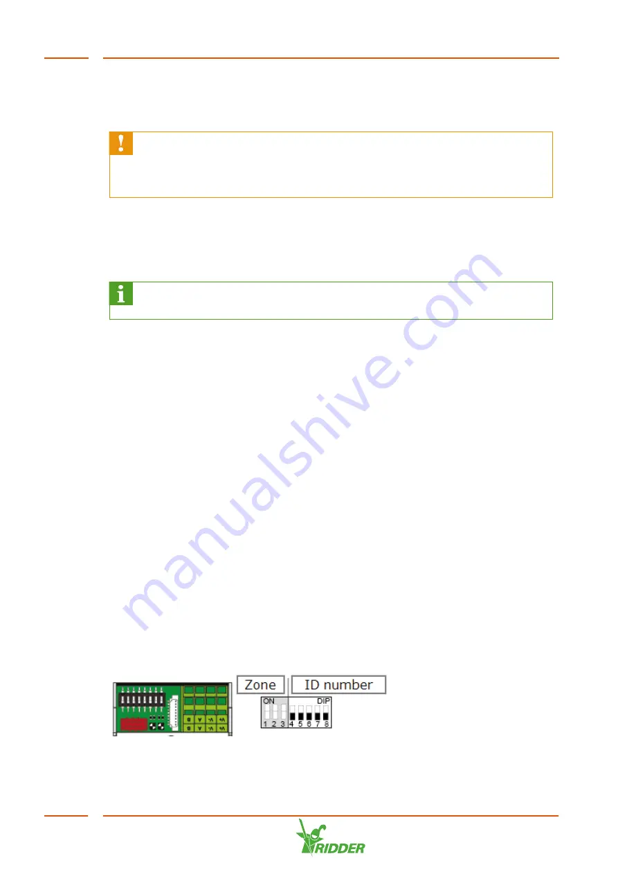
DIP switch
Up to 32 Smart Switches can be connected to the HortiMaX-Go!. The first step is to
assign addresses to the Smart Switches. Each Smart Switch requires a unique
address. This address is set with the DIP switch. By moving the small toggle switches
(or 'DIPs') up or down, you can set a binary number that will be used as the Smart
Switch address.
Figure 4-4:
DIP switch
HortiJet-Go!
30