


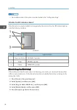


IP Address Setting
This section describes how to set an IP address on this option manually. Note that you can set an IP
address which is not only on the same network segment but also on a different network segment to share
a single printer with devices in multiple networks.
• You cannot change the IP address for this option from the operation panel of the main machine.
The setting must be done from a web browser on your PC.
• The network setting of this option is initially assigned as follows:
IP address: 192.168.100.100 / Subnet mask: 255.255.255.0
• The network setting of your PC must be in the same network segment to change the network setting
of this option.
1.
Make a note of the current network settings of your computer.
2.
Change the IP address on your PC to [192.168.100.xxx (*0 - 255)].
3.
Change the subnet mask on your PC to [255.255.255.0].
4.
Open a web browser.
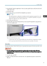
5.
Type [http://192.168.100.100/] in the address bar.
6.
Press the “Enter” key.
• The setting screen for this option appears.
7.
Click [Network Setting].
8.
Type [root] in the user name textbox and click [OK].
Controller Options
79
Summary of Contents for Z-P2
Page 1: ...Model Z P2 Machine Codes M257 Field Service Manual April 2015 ...
Page 2: ......
Page 30: ...1 Product Information 28 ...
Page 73: ...9 Install the securing holder E 10 Reassemble the machine Tray Heater 71 ...
Page 86: ...3 Preventive Maintenance 84 ...
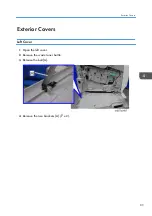
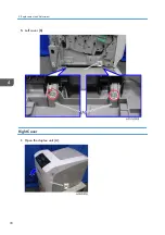
Page 92: ...5 Left cover B Right Cover 1 Open the duplex unit A 4 Replacement and Adjustment 90 ...
Page 128: ...5 Open the upper cover A 4 Replacement and Adjustment 126 ...
Page 131: ...4 The left stay A x 4 5 Rear holder bracket A x 2 Image Transfer 129 ...
Page 139: ...3 Remove the two screws 4 ID sensor board bracket A x 1 Image Transfer 137 ...
Page 141: ...4 Exit the SP mode Image Transfer 139 ...
Page 146: ...2 Temperature Humidity sensor A x 1 x 1 4 Replacement and Adjustment 144 ...
Page 187: ...3 Bracket A x 1 4 Release the paper feed unit A x 1 Paper Feed 185 ...
Page 201: ...5 Inner left upper cover page 94 6 Paper exit unit holder A x 1 Paper Exit 199 ...
Page 211: ...6 Release the left arm A x 1 Duplex Unit 209 ...
Page 215: ...3 Duplex lower guide plate A 4 Duplex upper guide plate A x 7 Duplex Unit 213 ...
Page 220: ...8 Right and left arms A x 2 each 4 Replacement and Adjustment 218 ...
Page 221: ...9 Duplex By pass motor bracket with the frame A x 6 10 Guide plate A x 4 Duplex Unit 219 ...
Page 245: ...5 Disconnect the connector 6 Disconnect the six connectors x 1 Electrical Components 243 ...
Page 254: ...4 Replacement and Adjustment 252 ...
Page 564: ...5 System Maintenance Reference 562 ...
Page 637: ...Model Z P2 Machine Codes M257 Appendices February 2015 ...
Page 638: ......
Page 640: ...2 ...
Page 648: ...1 Appendix Specifications 10 ...
Page 652: ...MEMO 14 ...
Page 653: ...MEMO 15 ...
Page 654: ...MEMO 16 EN ...