4.Replacement and Adjustment
149
The volume of the beeping sound is set to the same level as the speaker volume.
If the speaker volume is set to off, the volume of the beeping sound is set to its initial factory-set level.
If the machine does not beep, turn the main power OFF and then ON, and attempt data transfer again.
Try several times if necessary.
Be sure to check the transfer result after executing data transfer. If the transfer has failed, you need to
specify settings manually in the SP mode.
13.
When "Ready" is displayed on the control panel, turn the power OFF, and remove the AC power plug from the
receptacle.
14.
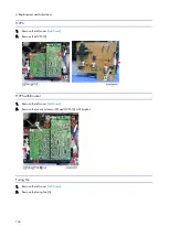
Disconnect the flat cable from both FCU boards.
15.
Remove the old FCU board with bracket from the controller box.
16.
Disconnect the speaker connector and remove the new FCU board [A] from the machine.
17.
Remove the bracket [B] from the old FCU board [A] and attach the bracket to the new FCU board.
18.
Mount the new FCU board in the machine and connect the speaker connector to the new FCU board.
19.
Reattach the controller box cover.
20.
Reattach the cover.
21.
Turn the main power ON.
22.
Enter the SP mode.
23.
Print the system parameter list from SP6-101 in the Fax SP menu, and then check the list to see whether the SRAM
data has been transferred correctly.
24.
Set the correct date and time from the [User Tools].
User Tools > Machine Features > System Settings > Timer Setting > Set Date/Time
If any of the SRAM data was not transferred, input those settings manually.
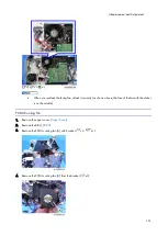
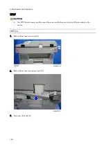
Speaker
1.
Remove the right cover (
2.
Remove the controller box cover [A]. (
Summary of Contents for M0A0
Page 2: ......
Page 10: ...8 ...
Page 12: ......
Page 34: ...2 Installation 22 9 Enter the password 10 Press OK 11 Enter the password again ...
Page 85: ...2 Installation 73 ...
Page 189: ...4 Replacement and Adjustment 177 ...
Page 203: ...5 System Maintenance 191 SP Mode Tables See Appendices ...
Page 229: ...5 System Maintenance 217 LDAP authorization information ...
Page 344: ...7 Detailed Descriptions 332 side guides from side to side ...
Page 358: ...7 Detailed Descriptions 346 ...
Page 368: ......
Page 558: ......
Page 574: ...1 Replacement and Adjustment 16 7 LCD A 4 8 Microphone A cushioning 1 ...
Page 622: ......
Page 624: ... A Short Edge Feed SEF B Long Edge Feed LEF ...
Page 626: ......
Page 632: ...1 Installation 6 ...
Page 752: ...5 Detailed Section Descriptions 126 Report Sample ...
Page 758: ...6 Specifications 132 Fax Unit Configuration Component No Remarks FCU 1 Speaker 2 ...
Page 760: ......
Page 762: ......
Page 776: ...2 Replacement and Adjustment 14 4 Detach the paper size switch from the bracket A Hook x2 ...


