


Before You Do
Safety Precautions
To prevent the creation of secondary problems by mishandling, observe the following precautions during
maintenance work.
1. Before starting disassembly/reassembly jobs, unplug the power cord and telephone line. In particular,
when having access to the power supply inside the machine, make sure that the power cord is
unplugged from the electrical outlet; when having access to the main PCB or NCU PCB, make sure
that both the power cord and telephone line are unplugged from the machine.
2. Be careful not to lose screws, washers, or other parts removed for parts replacement.
3. When using soldering irons and other heat-generating tools, take care not to damage the resin parts
such as wires, PCBs, and covers.
4. Static electricity charged in your body may damage electronic parts. When transporting PCBs, be
sure to wrap them in conductive sheets.
5. When replacing the PCB and all the other related parts, put on a grounding wrist band and perform
the job on a static mat. Also take care not to touch the conductor sections on the flat cables or on the
wire harness.
6. Be sure to reinsert self-tapping screws correctly, if removed.
7. Tighten screws to the torque values listed on the next page.
8. After disconnecting flat cables, check that each cable is not damaged at its end or shortcircuited.
9. When connecting flat cables, do not insert them at an angle. After insertion, check that the cables are
not at an angle.
10. When connecting or disconnecting cable connectors, hold the connector bodies not the wires. If the
connector has a lock, always slide the connector lock to unlock it.
11. Before reassembly, apply the specified lubricant to the specified points.
(Refer to Section 5.2 in this chapter.)
12. After repairs, check not only the repaired portion but also that the connectors and other related
portions function properly before operation checks.
13. After you use the machine, some internal parts are extremely HOT! To prevent injuries, be careful not
to put your fingers in the areas shown in the illustration.
4. Replacement and Adjustment
26
4
Summary of Contents for HL-F1
Page 1: ...Model HL F1 Machine Code H558 Field Service Manual 14 May 2010...
Page 2: ......
Page 13: ...1 Product Information Specifications See Appendices for the Specifications 11 1...
Page 15: ...Rear View 12 USB Interface Connector 13 Back Cover 14 AC Power Connector Overview 13 1...
Page 18: ...Components The equipment consists of the following major components 1 Product Information 16 1...
Page 22: ...2 Installation 20 2...
Page 23: ...3 Preventive Maintenance PM Tables There are no PM parts for this machine 21 3...
Page 24: ...3 Preventive Maintenance 22 3...
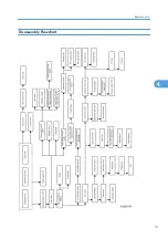
Page 33: ...Disassembly Flowchart Before You Do 31 4...
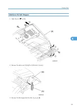
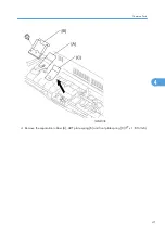
Page 44: ...5 Remove the actuator R A from the panel unit B 4 Replacement and Adjustment 42 4...
Page 45: ...6 Release the four hooks to remove the panel rear cover A x 3 B M3x8 Common Parts 43 4...
Page 48: ...11 Remove the rubber key A 4 Replacement and Adjustment 46 4...
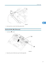
Page 60: ...22 Remove the CIS A 23 Disconnect the CIS harness A 4 Replacement and Adjustment 58 4...
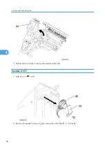
Page 61: ...24 Remove the two CIS springs A 25 Remove the LF roller gear A Common Parts 59 4...
Page 63: ...28 Remove the scanning motor F sub ASSY A x 1 M3x6 Common Parts 61 4...
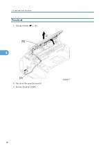
Page 107: ...2 Remove the main frame R A x 3 B M4x12 Main Body 105 4...
Page 110: ...FG harness ASSY 1 Main PCB 2 FG harness ASSY 3 Laser unit 4 Replacement and Adjustment 108 4...
Page 111: ...Regist sensor PCB ASSY 1 PS PCB unit 2 Regist sensor PCB ASSY 3 Chute Harness Routing 109 4...
Page 112: ...Fan Motor 60 Unit 1 Fan motor 60 unit 2 Main PCB 4 Replacement and Adjustment 110 4...
Page 120: ...CIS 1 Main PCB 2 CIS 4 Replacement and Adjustment 118 4...
Page 155: ...10 Click Next Firmware Installation 153 5...
Page 156: ...11 To proceed click Yes 5 Service Maintenance 154 5...
Page 218: ...Image Defects 6 Troubleshooting 216 6...
Page 255: ...Model HL F1 Machine Code H558 Appendices 14 May 2010...
Page 256: ......
Page 258: ...2...