


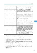


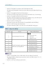


Setting all of these selectors to "1" activates the dial tone detection function so that the machine starts
dialing upon detection of a dial tone when a line is connected. (However, in those countries which
support no dial tone detection function, e.g., in the U.S.A., setting these selectors to "1" makes the
machine start dialing after a WAIT of 3.5 seconds.) For the detecting conditions of the
1st dial tone, refer to WSW07 and WSW08.
Other setting combinations deactivate the dial tone detection function so that the machine starts dialing
after the specified WAIT (3.5, 7.0, 10.5, 14.0, 17.5, 21.0, or 24.5 seconds) without detection of a
dial tone when a line is connected to the PSTN.
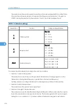
• Selector 4: Max. pause time allowable for remote ID code detection
This selector sets the maximum pause time allowable for detecting the second digit of a remote ID
code after detection of the first digit in remote reception.
If selector 4 is set to "0" (2 seconds), for instance, only a remote ID code whose second digit is detected
within 2 seconds after detection of the first digit will become effective so as to activate the remote
function.
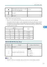
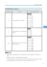
• Selectors 5 and 6: Busy tone detection in automatic sending mode
These selectors determine whether or not the machine automatically disconnects a line upon detection
of a busy tone in automatic sending mode.
Setting selector 6 to "0" ignores a busy tone so that the machine does not disconnect the line.
Setting selectors 5 and 6 to "0" and "1," respectively, makes the machine detect a busy tone only
after dialing and disconnect the line.
Setting both of selectors 5 and 6 to "1" makes the machine detect a busy tone before and after dialing
and then disconnect the line.
• Selector 7: Busy tone detection in automatic receiving mode
This selector determines whether or not the machine automatically disconnects the line upon detection
of a busy tone in automatic receiving mode.
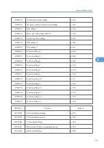
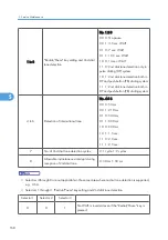
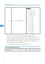
WSW06 (Redial/Pause key setting and 2nd dial tone detection)
Selector No.
Function
Setting and Specifications
Firmware Switches (WSW)
167
5
Summary of Contents for HL-F1
Page 1: ...Model HL F1 Machine Code H558 Field Service Manual 14 May 2010...
Page 2: ......
Page 13: ...1 Product Information Specifications See Appendices for the Specifications 11 1...
Page 15: ...Rear View 12 USB Interface Connector 13 Back Cover 14 AC Power Connector Overview 13 1...
Page 18: ...Components The equipment consists of the following major components 1 Product Information 16 1...
Page 22: ...2 Installation 20 2...
Page 23: ...3 Preventive Maintenance PM Tables There are no PM parts for this machine 21 3...
Page 24: ...3 Preventive Maintenance 22 3...
Page 33: ...Disassembly Flowchart Before You Do 31 4...
Page 44: ...5 Remove the actuator R A from the panel unit B 4 Replacement and Adjustment 42 4...
Page 45: ...6 Release the four hooks to remove the panel rear cover A x 3 B M3x8 Common Parts 43 4...
Page 48: ...11 Remove the rubber key A 4 Replacement and Adjustment 46 4...
Page 60: ...22 Remove the CIS A 23 Disconnect the CIS harness A 4 Replacement and Adjustment 58 4...
Page 61: ...24 Remove the two CIS springs A 25 Remove the LF roller gear A Common Parts 59 4...
Page 63: ...28 Remove the scanning motor F sub ASSY A x 1 M3x6 Common Parts 61 4...
Page 107: ...2 Remove the main frame R A x 3 B M4x12 Main Body 105 4...
Page 110: ...FG harness ASSY 1 Main PCB 2 FG harness ASSY 3 Laser unit 4 Replacement and Adjustment 108 4...
Page 111: ...Regist sensor PCB ASSY 1 PS PCB unit 2 Regist sensor PCB ASSY 3 Chute Harness Routing 109 4...
Page 112: ...Fan Motor 60 Unit 1 Fan motor 60 unit 2 Main PCB 4 Replacement and Adjustment 110 4...
Page 120: ...CIS 1 Main PCB 2 CIS 4 Replacement and Adjustment 118 4...
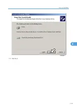
Page 155: ...10 Click Next Firmware Installation 153 5...
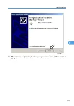
Page 156: ...11 To proceed click Yes 5 Service Maintenance 154 5...
Page 218: ...Image Defects 6 Troubleshooting 216 6...
Page 255: ...Model HL F1 Machine Code H558 Appendices 14 May 2010...
Page 256: ......
Page 258: ...2...