


2. Upon completion of parameter initialization, the machine returns to the initial stage of the maintenance
mode.
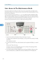
3. Be sure to turn the machine power off. If you press the "9" key twice to exit from the maintenance
mode without turning the power off, then the machine will not fully initialize the EEPROM.
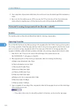
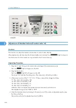
Printout of Scanning Compensation Data (Function code 05)
Function
The machine prints out the white and black level data for scanning compensation.
Operating Procedure
Do not start this function merely after powering on the equipment but start it after carrying out a sequence
of scanning operation. Unless the equipment has carried out any scanning operation, this function cannot
print out correct scanning compensation data. This is because at the start of scanning operation, the
equipment initializes white and black level data and takes in the scanning compensation reference data.
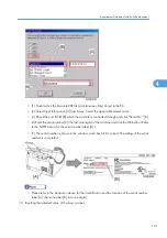
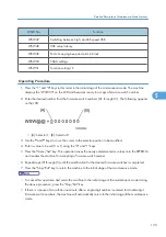
1. Press the "0" and "5" keys in this order in the initial stage of the maintenance mode.
The "WHITE LEVEL 1" will appear on the LCD.
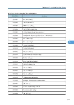
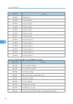
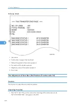
2. The equipment prints out the scanning compensation data list containing the following:
a) Bright output adjustment value 1Byte
b) Illuminant adjustment value 1Byte
c) Black level MIN data 1Byte
d) Black level MAX data 1Byte
e) White level MIN data 1Byte
f) White level MAX data 1Byte
g) Background color compensated data 1Byte
h) Black level data 1664Byte
i) White level data 1664Byte
3. Upon completion of recording of the compensation data list, the equipment returns to the initial stage
of the maintenance mode.
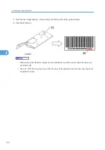
• If any data is abnormal, its code will be printed in inline style, as shown on the next page.
5. Service Maintenance
130
5
Summary of Contents for HL-F1
Page 1: ...Model HL F1 Machine Code H558 Field Service Manual 14 May 2010...
Page 2: ......
Page 13: ...1 Product Information Specifications See Appendices for the Specifications 11 1...
Page 15: ...Rear View 12 USB Interface Connector 13 Back Cover 14 AC Power Connector Overview 13 1...
Page 18: ...Components The equipment consists of the following major components 1 Product Information 16 1...
Page 22: ...2 Installation 20 2...
Page 23: ...3 Preventive Maintenance PM Tables There are no PM parts for this machine 21 3...
Page 24: ...3 Preventive Maintenance 22 3...
Page 33: ...Disassembly Flowchart Before You Do 31 4...
Page 44: ...5 Remove the actuator R A from the panel unit B 4 Replacement and Adjustment 42 4...
Page 45: ...6 Release the four hooks to remove the panel rear cover A x 3 B M3x8 Common Parts 43 4...
Page 48: ...11 Remove the rubber key A 4 Replacement and Adjustment 46 4...
Page 60: ...22 Remove the CIS A 23 Disconnect the CIS harness A 4 Replacement and Adjustment 58 4...
Page 61: ...24 Remove the two CIS springs A 25 Remove the LF roller gear A Common Parts 59 4...
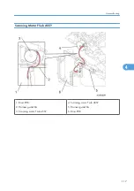
Page 63: ...28 Remove the scanning motor F sub ASSY A x 1 M3x6 Common Parts 61 4...
Page 107: ...2 Remove the main frame R A x 3 B M4x12 Main Body 105 4...
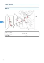
Page 110: ...FG harness ASSY 1 Main PCB 2 FG harness ASSY 3 Laser unit 4 Replacement and Adjustment 108 4...
Page 111: ...Regist sensor PCB ASSY 1 PS PCB unit 2 Regist sensor PCB ASSY 3 Chute Harness Routing 109 4...
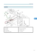
Page 112: ...Fan Motor 60 Unit 1 Fan motor 60 unit 2 Main PCB 4 Replacement and Adjustment 110 4...
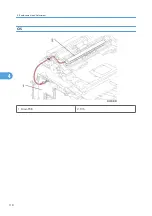
Page 120: ...CIS 1 Main PCB 2 CIS 4 Replacement and Adjustment 118 4...
Page 155: ...10 Click Next Firmware Installation 153 5...
Page 156: ...11 To proceed click Yes 5 Service Maintenance 154 5...
Page 218: ...Image Defects 6 Troubleshooting 216 6...
Page 255: ...Model HL F1 Machine Code H558 Appendices 14 May 2010...
Page 256: ......
Page 258: ...2...