2.
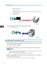
Click [Control Panel].
3.
Click [Hardware and Sound].
4.
Click [Change when the computer sleeps].
5.
Make sure [Put the computer to sleep] is set to "Never".
• Follow the procedure below to check that the SNMP status is invalid.
Click [Printer (Driver) Property Setting] > [Port] > [Port Configuration] > uncheck [Enable SNMP
Status]
• For procedures to check power options for other operating systems, refer to their respective Help.
• Make sure the printer's power is turned on and the network or USB cable remains connected
during updates.
• When operating in the recovery mode, connect the USB cable only and make sure that the printer
is not connected to the network.
• Do not print any jobs or run applications that use the printer driver or SmartDeviceMonitor during
updates.
• If you want to use the SmartDeviceMonitor port to update the firmware over a network, be sure to
clear the [Use Extended Features] check box of SmartDeviceMonitor for Client.
• Check the engine boot version to update.
If an update is executed with wrong boot version, and when a recovery firmware update is
executed, the screen freezes with a message "Updating firmware...". Besides, the update fails.
* The boot version is shown as numbers following the colon of the engine version. For example, the
boot version of "1.03:05" is "05".
• When an engine firmware update is executed while the SC670-00 occurs, the screen freezes with
a message "Updating firmware...". Besides, the update fails.
Items Required for Updating the Firmware
• USB cable or Ethernet crossover cable
In the recovery mode, only the USB cable can be used.
• The controller firmware update tool
• The engine firmware update tool ("Engine firmware serial number”.exe)
Update Procedure
Before you start updates, ensure the following:
• The printer is connected to the computer with a USB cable or via a peer-to-peer network.
• The printer driver of the printer for which you want to update the firmware is installed properly in
the computer.
Updating the Firmware
125
Summary of Contents for Gim-MF1a
Page 1: ...Model Gim MF1a b Machine Code M172 M173 Field Service Manual September 2014...
Page 2: ......
Page 32: ...2 Installation 30...
Page 46: ...2 Operation Panel A x 5 4 Replacement and Adjustment 44...
Page 105: ...2 Rear Cover Switch A x 1 Hook Electrical Components 103...
Page 122: ...5 Operation Panel page 43 Operation Panel 4 Replacement and Adjustment 120...
Page 125: ...Service Program Mode 123...
Page 184: ...6 Troubleshooting 182...
Page 192: ...MEMO 190...
Page 193: ...MEMO 191...
Page 194: ...MEMO 192 EN...
Page 195: ...Model Gim MF1a b Machine Code M172 M173 Appendices September 2014...
Page 196: ......
Page 214: ...1 Appendices Specifications 18...
Page 299: ...MEMO 103...
Page 300: ...MEMO 104 EN...


