background image

76

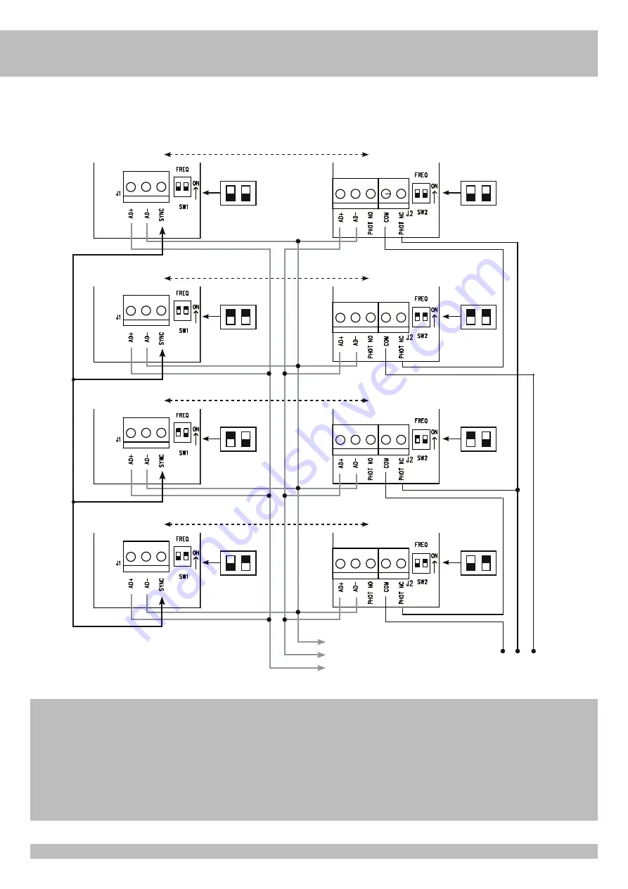
COLLEGAMENTI FOTOCELLULE - CONNEXIONS PHOTOCELLULE - PHOTOCELLS CONNECTIONS 

FOTOZELLEN VERBINDUNGEN - CONEXIONES FOTOCÉLULAS

4 fotocellule NOVA sincronizzate con autotest
4 photocellules NOVA synchronisées avec autotest
4 NOVA photocells synchronized with self-test
4 NOVA Photozellen synchronisiert mit Selbstkontrolle
4 fotocélulas NOVA sincronizadas con autotest

TX3

RX3

TX2

RX2

TX1

RX1

TX4

RX4

A-

A+

A+ TEST

COM A+

PHOT1 PHOT2

ATTENZIONE:  Se si attiva la funzione AUTOTEST e si collega una sola fotocellula, si 

deve fare un ponticello tra i morsetti PHOT 1 e PHOT 2. Se il ponticello 

non viene eseguito, l'autotest fallisce ed il cancello non si muoverà.

AVERTISSEMENT:  si la fonction AUTOTEST est activée et qu'une seule  photocellule 

est connectée, un cavalier doit être créé entre les bornes PHOT 1 

et PHOT 2. Si le cavalier n'est pas exécuté, l'autotest échoue et le 

portail ne bouge pas.

WARNING:  If the AUTOTEST feature is enabled and only one photocell is connected, 

a jumper must be made between the PHOT 1 and PHOT 2 terminals. If the 

jumper is not made, the AUTOTEST fails and the gate will not move.

WARNUNG:  

Wenn die AUTOTEST-Funktion aktiviert und nur eine Fotozelle 

angeschlossen ist, muss eine Brücke zwischen den Klemmen PHOT 1 

und PHOT 2 hergestellt werden. Wenn der Jumper nicht gemacht wird, 

schlägt der AUTOTEST fehl und das Gate bewegt sich nicht.

ADVERTENCIA:  Si la función AUTOTEST está activada y solo se conecta una 

fotocélula, se debe hacer un puente entre los terminales PHOT 1 y 

PHOT 2. Si el puente no se ejecuta, la autoprueba falla y la puerta no 

se moverá.

Summary of Contents for AA50130

Page 1: ...ni con il prodotto CE PRODUIT EST DÉDIÉ AU CONTRÔLE DU TRAFIC VÉHICULAIRE ET NON À CELUI DES PIÉTONS Il est donc conseillé d appliquer les règles de sécurité demandées et de signaler le danger par un ou plusieurs panneaux ACG9624 afin d éviter tout contact entre les piétons et le produit THIS OPERATOR IS DESIGNED FOR THE VEHICLES ACCESS CONTROL AND NOT FOR PEDESTRIANS Therefore we higly recommend ...

Page 2: ...anza nell installazione delle norme di sicurezza e delle leggi attualmente in vigore ATTENTION POUR LA SECURITE DES PERSONNES IL EST IMPORTANT DE SUIVRE TOUTES LES INSTRUCTIONS CONSERVER SOIGNEUSEMENT CES INSTRUCTIONS 1 Si ce n est pas prévu dans la centrale installer en amont de celle ci un interrupteur de type magnétothermique omnipolaire avec ouverture minimum des contacts de 3 mm qui porte une...

Page 3: ...aused by the non observance during the installation of the safety standards and of the laws in force at present ACHTUNG FÜR DIE SICHERHEIT DER PERSONEN IST ES WICHTIG DASS ALLE ANWEISUNGEN GENAU AUSGEFÜHRT WERDEN INSTALLATIONSVORSCHRIFTEN BEACHTET WERDEN 1 Wenn nicht bereits an der elektrischen Schaltzentrale vorgesehen muss vor der Schaltzentrale ein thermomagnetischer Schalter installiert werden...

Page 4: ...o dell acquisto di una nuova apparecchiatura di tipo equivalente Presso i distributori di prodotti elettronici con superficie di vendita di almeno 400 m2 è inoltre possibile consegnare gratuitamente senza obbligo di acquisto i prodotti elettronici da smaltire con dimensioni inferiori a 25 cm L adeguata raccolta differenziata per l avvio successivo dell apparecchiatura dismessa al riciclaggio al tr...

Page 5: ...tezione IP 54 FISSAGGIO RAPID S Dopo aver cementato il basamento di fissaggio cod ACG8110 nella posizione ritenuta ideale procedere nel fissaggio della RAPID S utilizzando i dadi in dotazione e una chiave esagonale n 19 Misure in mm 1 Barriera RAPID S 2 Fotocellule di sicurezza 3 Colonnina porta fotocellula zincata 4 Costa a fotocellula 5 Sensore magnetico LAYOUT IMPIANTO I Componenti da installar...

Page 6: ...8611 ACG8285 n 2 ACG8641 Ø 4 5 n 1 ACG8640 Ø 4 20 Asta Ø 80 RIB e rastrelliera ACG8501 ACG8548G ACG8291B n 2 ACG8641 Ø 4 5 20 Asta Ø 80 RIB e rastrellierA magnete ACG8501 ACG8548G ACG8291B ACG8073G n 2 ACG8641 Ø 4 5 n 1 ACG8640 Ø 4 20 Asta Ø 80 RIB e rastrellierA pendulo ACG8501 ACG8548G ACG8291B ACG8285 n 2 ACG8641 Ø 4 5 n 1 ACG8640 Ø 4 20 Asta Ø 80 RIB e fotocostA magnete ACG8501 ACG8548G ACG709...

Page 7: ...assemblata nel tubo centrale Fig 8 Calzare il bilanciere inferiore in modo che la superficie dei due inserti plastici vada a contatto con le molle laterali Fig 9 Avvitare la prima ghiera in modo che il lato con la superficie liscia più grande vada a contatto con il bilanciere Fig 10 N B AVVITARE LA GHIERA COME DA TABELLA A PAGINA 6 TIRAGGIO H con l apposita chiave in dotazione Avvitare la seconda ...

Page 8: ...l movimento ideale dell asta In caso di errato livellamento della piastra da cementare l asta potrebbe non risultare perfettamente orizzontale o verticale con un conseguente cattivo risultato estetico dell installazione Per ovviare a ciò è possibile modificare la corsa dell asta intervenendo sui finecorsa meccanici Fig 7 1 A barriera sbloccata utilizzare una chiave esagonale n 19 per sbloccare i d...

Page 9: ...forza MANUTENZIONE Da effettuare solamente da parte di personale specializzato dopo aver tolto l alimentazione elettrica al motore Ogni 100 000 manovre complete verificare il bilanciamento dell asta vedi capitolo REGOLAZIONE MOLLE DI BILANCIAMENTO il serraggio della manopola di sblocco vedi capitolo SBLOCCO DI EMERGENZA il serraggio del mozzo e il fissaggio dell asta vedi capitolo MONTAGGIO ASTA l...

Page 10: ...GIATORE 230Vac 40W ALIMENTAZIONE 230Vac 50 Hz OROLOGIO OPEN 2 CHIUDE OK CLOSE IMPULSO SINGOLO OPEN 1 24Vdc 0 4A 15 24Vdc 0 4A 15 A TEST A AUTOTEST FOTOCELLULE LED R 2 2K 1 4W FINECORSA CHIUSURA FINECORSA APERTURA FINECORSA RALL CHIUDE FINECORSA RALL APRE COMUNE COMUNE COMUNE COMUNE FOTOCELLULA 1 STOP SENSORE MAGNETICO ENTRATA FOTOCELLULA 2 COSTA 700 W MAX ...

Page 11: ...rsa per inizio rallentamento in chiusura NO LSSO Contatto finecorsa per inizio rallentamento in apertura NO J15 COM A Comune dei contatti Positivo 24 Vdc OK CLOSE Contatto comando chiusura immediata solo in modalità PARK B I O Contatto orologio START Contatto impulso singolo NA CLOSE Contatto impulso di chiusura NA OPEN 2 Contatto impulso di apertura 2 NA per uscire solo in modalità PARK OPEN 1 Co...

Page 12: ...APRE ED IN CHIUDE Questocontrollohailcompitodiagevolarel installatoredurantelamessainoperadell impianto o durante eventuali controlli successivi 1 Mettere DIP 1 su ON il led rosso DL1 inizia a lampeggiare 2 Premere e mantenere premuto il pulsante PROG il movimento è eseguito ad uomo presente apre stop chiude stop apre ecc Con il led verde DL2 acceso la sbarra si apre Con il led rosso DL4 acceso la...

Page 13: ...spento FUNZIONAMENTO IN MODALITÀ PARK DIP 6 ON Tutti i comandi sono abilitati La gestione di 2 semafori è possibile PULSANTE DI APERTURA PER ENTRARE NEL PARCHEGGIO COM A OPEN 1 A barriera ferma il pulsante comanda il movimento di apertura Se viene premuto durante la chiusura fa riaprire la barriera A condizione che un veicolo sia presente sul sensore magnetico TLC attivo può essere comandata l ape...

Page 14: ...l pulsante di STOP non è considerato una sicurezza da bypassare in questa modalità pertanto se viene premuto o è rotto non consente alcuna manovra La manovra con comando mantenuto è esclusivamente una manovra di emergenza che deve essere effettuata per brevi periodi e con la sicurezza visiva del movimento dell automatismo Appenapossibileleprotezioniguastedevonoessereripristinateperuncorrettofunzio...

Page 15: ... smartphone Spento Spento Led DL12 acceso fisso verde I cicli impostati sono stati raggiunti 6 Toni ogni 5 ss Si rinnova dando un comando Spento Nessun led abbinato Risparmio energetico attivato da smartphone Spento Spento Led blu lampeggia 1 volta ogni 5 s Allarme mancato raggiungimento finecorsa o barriera sbloccata 5 Toni Lampeggia per 1 minuto Nessun led abbinato DIFETTO SOLUZIONE Dopo aver ef...

Page 16: ...A Per apertura con automezzi monocanale 230 Vac cod ACG9060 monocanale 12 24 Vac dc cod ACG9063 bicanale 12 24 Vac dc cod ACG9064 ASTA SNODATA L 3 m cod ACG8223 L 4 m cod ACG8224 ATTENZIONE per ASTA SNODATA di lunghezza superiore a 4 metri si consiglia l impiego di RAPID N COSTA A FOTOCELLULA SU ASTA Ø80 cod ACG8611 ACG7090 PALETTO DI SUPPORTO Paletto di supporto a forcella compatibile con tutte l...

Page 17: ...PER LUCE BOX cod ACQ9080 SCHEDA A 3 RELÉ PER LUCE BOX o GESTIONE 2 SEMAFORI cod ACQ9081 SYNCRO Schede di sincronizzazione dei comandi e delle sicurezze di 2 L1 o P1 cod ACG8081 Sincronizzazione attivabile solo con App RIB GATE SAIL SAIL arancio con scheda intermittente incorporata cod ACG7072 SAIL bianco con scheda intermittente incorporata cod ACG7078 SUPPORTO LATERALE SAIL cod ACG8054 47 5 102 5...

Page 18: ...si APP8050 Scheda APP per gestire la centrale di comando tramite Bluetooth APP8054 Scheda APP per gestire la centrale di comando tramite Bluetooth APP8064 Modulo Wi Fi per Scheda APP per gestire la centrale tramite rete Wi Fi locale WLAN APP8066 Modulo RJ45 per Scheda APP per gestire la centrale tramite rete dati locale LAN ...

Page 19: ...otection IP IP 54 FIXATION DE LA RAPID S Après avoir cimenté l embase de fixation dans la position que vous jugerez idéale passer à la fixation de la RAPID S en utilisant les écrous fournis et une clef hexagonale n 19 Mesures en mm 1 Barrière RAPID S 2 Photocellules p protection 3 Poteau zingué p cellule 4 Barre palpeuse avec Photocellule 5 Boucle magnetique 280 x 300 3000 4000 1065 1000 F SCHÉMA ...

Page 20: ...G8611 ACG8283 n 2 ACG8641 Ø 4 5 n 1 ACG8640 Ø 4 20 Lisse Ø 80 RIB avec ridelle ACG8501 ACG8548G ACG8291B n 2 ACG8641 Ø 4 5 20 Lisse Ø 80 RIB avec ridelle magnéto ACG8501 ACG8548G ACG8291B ACG8073G n 2 ACG8641 Ø 4 5 n 1 ACG8640 Ø 4 20 Lisse Ø 80 RIB avec ridelle fourche escamotable ACG8501 ACG8548G ACG8291B ACG8283 n 2 ACG8641 Ø 4 5 n 1 ACG8640 Ø 4 20 Lisse Ø 80 RIB avec fotocosta magnéto ACG8501 A...

Page 21: ...e assemblé dans le tube central Fig 8 Fixer le balancier inférieur de façon à ce que surface des deux inserts en plastique soit en contact avec les deux ressorts latéraux Fig 9 Visser la première bague de façon à ce que le côté ayant la surface lisse plus grande soit en contact avec le balancier Fig 10 N B VISSER LA BAGUE COMME INDIQUÉ AU TABLEAU À LA PAGE 20 TIRAGE H avec la clé fournie en dotati...

Page 22: ... de course déjà réglés de façon à imprimer à la lisse le mouvement idéal En cas de nivellement erroné de la plaque à cimenter la lisse pourrait ne pas arriver parfaitement horizontale ou verticale ce qui compromettrait le résultat esthétique de l installation Pour éviter ce problème il est possible de modifier la course de la lisse en intervenant sur les fins de course mécaniques Fig 7 1 Sur barri...

Page 23: ...nu on tourne à fond la clé dans le sens anti horarie ENTRETIEN Effectuer soulement par personnel specialisé après avoir coupé l alimentation Toutes les 100 000 manoeuvres complètes vérifier l équilibrage de la lisse voir le paragraphe RÉGLAGE DES RESSORTS D ÉQUILIBRAGE le serrage de la poignée de déblocage voir le paragraphe PROCÉDURE DE DÉBLOCAGE D URGENCE de moyeu porte lisse et le fixation de l...

Page 24: ...E 2 FERMETURE OK FERMETURE COMMANDE UNIQUE OUVERTURE 1 24Vdc 0 4A 15 24Vdc 0 4A 15 A TEST A AUTOTEST PHOTOCELLULES LED R 2 2K 1 4W FIN FERMETURE FIN OUVERTURE FIN RALL FERMETURE FIN RALL OUVERTURE COMMUN PHOTOCELLULES 1 STOP CAPTEUR MAGNETIQUE D ENTRÉE PHOTOCELLULES 2 CORDON COMMUN COMMUN COMMUN 700 W MAX P1 cod AC08086 230 V 50 60 Hz P1 cod AC08087 120 V 60 Hz ...

Page 25: ... pour début de ralentissement en fermeture NO LSSO Contact fin de course pour début de ralentissement en ouverture NO J15 COM A Commun des contacts Positif 24 Vdc OK CLOSE Commande de contact de fermeture immédiate uniquement en mode PARK B I O Contact horloge NO START Contact à une seule impulsion NO CLOSE Contact de fermeture NO OPEN 2 Contact poussoir d ouverture 2 NA pour sortir uniquement en ...

Page 26: ... R AUX avec un emetteur en exécutant la procédure de mémorisation décrite au point E C RÉGLAGE DU RALENTISSEMENT DE LA BARRIÈRE EN OUVERTURE ET FERMÉTURE Ce contrôle a pour but d aider l installateur lors de la mise en place de l installation ou lors d éventuels contrôles futurs 1 Positionner DIP 1 sur ON la LED rouge DL1 commence à clignoter 2 Presser le bouton poussoir PROG et le maintenir enfon...

Page 27: ...l horloge reste active Lorsque l automatisation est ouverte toutes les fonctions de contrôle sont inhibées Lorsque le disjoncteur est relâché ou à la fin du temps imparti l automatisme se ferme immédiatement BOUTON DE FERMETURE COM A CLOSE Lorsque la barrière est arrêtée le mouvement de fermeture commande GESTION 1 FEU DE CIRCULATION AVEC 1 RELAIS CARTE 3 ACQ9081 ET 1 FEU DE CIRCULATION ACG5513 Lo...

Page 28: ...e 60 secondes les commandes OPEN1 OPEN 2 CLOSE et START fonctionnent seulement con commande maintenue La signalisation de l activation de cette opération est donnée par la LED DL1 qui clignote Le contrôle radio et la fermeture automatique sont exclues parce que leur fonctionnement n est pas autorisé par les règles A la restauration du contact de sécurité l opération est restaurée après une seconde...

Page 29: ...nge pendant 10 s Programmation correcte des codes radio pour l ouverture et R AUX 1 Tonalité Éteint S allume en vert une fois Code radio non contenu dans la mémoire Éteint Éteint Flash rouge Mémoire saturée en codes radio 1000 codes mémorisés Éteint Éteint Effectue 6 clignotements verts Suppression codes pour l ouverture et R AUX 2 Tonalités Éteint Effectue 2 clignotements verts SIGNALISATIONS PEN...

Page 30: ...e débrancher tous les connecteurs amovibles et de les brancher un par un afin d identifier plus facilement la cause du défaut Vérifier l intégrité de fusible F1 En cas de fusible en panne en utiliser uniquement de valeur adéquate F1 T 5A Fusible de protection du moteur La barriere ouvre et ferme mais n a pas de force et se déplace lentement Vérifier le réglage des trimmers LOW SPEED OPEN et LOW SP...

Page 31: ... support en fourche compatible avec toutes les tiges code ACG9130G CARTE À 1 RELAI POUR BOîTE DE LUMIÈRE code ACQ9080 CARTE À 3 RELAIS POUR BOîTE DE LUMIÈRE OU GESTION DES 2 FEUX code ACQ9081 EMETTEUR RADIO SUN SUN 2CH cod ACG6052 SUN 4CH cod ACG6054 SUN CLONE 2CH cod ACG6056 SUN CLONE 4CH cod ACG6058 SUN PRO 2CH cod ACG6210 SUN PRO 4CH cod ACG6214 MODULE RADIO 433MHz cod ACG8069 ...

Page 32: ...e RJ45 pour Carte APP pour gérer le tableau de contrôle via un réseau de données local LAN SAIL SAIL orange avec panneau clignotant intégré code ACG7072 SAIL blanc avec panneau clignotant intégré code ACG7078 SUPPORT LATÉRAL SAIL code ACG8054 47 5 102 5 126 35 146 SYNCRO Cartes pour la synchronisation des commandes et des sécurités de 2 L1 ou P1 code ACG8081 Synchronisation activée uniquement avec...

Page 33: ... Working Temperature C 10 55 Protection IP IP 54 ASSEMBLING RAPID S Afteryouhavecementedinthebaseplatewhereyouwantit mountRAPIDSusing the nuts provided and a no 19 hexagonal wrench 1 280 11 2 x300 12 3000 118 4000 157 1065 42 1000 39 Measurements in mm inch 1 RAPID S barrier 2 Photoelectric cells 3 Galvanized column for P E cells 4 Strip with Photoelectric cells 5 Magnetic loop Parts to install ac...

Page 34: ...548G ACG7090 ACG8611 ACG8283 n 2 ACG8641 Ø 4 5 n 1 ACG8640 Ø 4 20 Ø 80 RIB Boom and hanging rack ACG8501 ACG8548G ACG8291B n 2 ACG8641 Ø 4 5 20 Ø 80 RIB Boom and hanging rack magnet ACG8501 ACG8548G ACG8291B ACG8073G n 2 ACG8641 Ø 4 5 n 1 ACG8640 Ø 4 20 Ø 80 RIB Boom and hanging rack hanging support ACG8501 ACG8548G ACG8291B ACG8283 n 2 ACG8641 Ø 4 5 n 1 ACG8640 Ø 4 20 Ø 80 RIB Boom and fotocosta ...

Page 35: ...alancing springs into the side pipes Pic 7 Fit the central balancing spring into the central pipe Pic 8 Fit the lower balancing unit in a way that its two plastic elements touch the side springs Pic 9 Screw the first ring nut in a way that its side with the larger smooth surface touches lower balancing unit Pic 10 N B SCREW THE RING NUT AS SHOWN IN THE TABLE ABOVE TENSION H with the supplied wrenc...

Page 36: ...alanced perfectly disengage the boom arm from the gearmotor and move the boom by hand The boom should slightly tend to rise LIMIT SWITCH SETTING The barrier is supplied with the electrical limit switches and the mechanical stoppers already set to allow optimum boom arm movement If the base plate cannot be cemented on a horizontal plane the boom might be not perfectly horizontal or vertical To avoi...

Page 37: ...ou block it MAINTENANCE To be undertaken only by specialized staff after disconnecting power supply After every 100 000 cycles check boom balance see the paragraph ADJUSTING THE BALANCING SPRINGS the tightness of the release knob see the paragraph EMERGENCY RELEASE the tightness of the boom holding attachment and the implantation of the boom see the paragraph ASSEMBLING THE BOOM the wear on the me...

Page 38: ...CLOSE SINGLE COMMAND OPEN 1 24Vdc 0 4A 15 24Vdc 0 4A 15 A TEST A PHOTOCELLS AUTO TEST LED R 2 2K 1 4W LIMIT SWITCH CLOSE LIMIT SWITCH OPEN LIMIT SWITCH LOW SPEED CLOSE LIMIT SWITCH LOW SPEED OPEN COMMON PHOTOCELL 1 STOP MAGNETIC LOOP ON ENTRANCE PHOTOCELL 2 EDGE COMMON COMMON COMMON 700 W MAX P1 cod AC08086 230 V 50 60 Hz P1 cod AC08087 120 V 60 Hz ...

Page 39: ...Opening limit switch contact NC LSSC Closing slowing down limit switch contact NO LSSO Opening slowing down limit switch contact NO J15 COM A Common contacts Positive 24 Vdc OK CLOSE Immediate closure command contact only when switched to PARK mode B I O Contact NO dedicated to a timer START Single pulse contact NO CLOSE Closing impulse contact NO OPEN 2 Opening impulse contact NO to exit only in ...

Page 40: ... This check is meant to facilitate the installer during the start up of the system or for any other future controls 1 Turn DIP 1 to ON the red led DL1 starts blinking 2 Press the PROG button and hold it movement is now performed in hold to run mode open stop close stop open etc If the GREEN led DL2 is on the boom arm opens If the RED led DL4 is on the boom arm closes 3 Carry out the slow down spee...

Page 41: ... inversion of the barrier in the opening even if the vehicle remains in their range of action OPENING BUTTON TO EXIT THE PARKING COM A OPEN 2 with priority management and signaling of traffic lights When the barrier is still the magnetic sensor or other device connected to OPEN 2 controls the opening movement The barrier will remain open until the vehicle passes through the photocells located at t...

Page 42: ...of radio codes SIGNAL OPEN BARRIER WARNING LIGHT 12 Vdc 3 W MAX SIGN SIGN It has the task of signaling when the barrier is open partially open or in any case not completely closed It turns OFF only when the barrier is completely closed During the opening SIGNAL flashes slowly When the barrier is still or open SIGNAL is switched on permanently During the closing SIGNAL flashes quickly N B Max 3 W I...

Page 43: ...artphone OFF OFF Led DL12 is steady on green Achievement of set cycles 6 Tones every 5 s It is renewed by giving a command OFF No leds matched Energy saving activated by smartphone OFF OFF Blue led flashes once every 5 s Alarm no limit switches reached or unlocked barrier 5 Tones Flashes for 1 minute No leds matched FAULT SOLUTION After having carried out the various connections and having supplie...

Page 44: ...els 12 24 Vac dc code ACG9064 G B ACCESSORIES For the connections and the technical data of the optional equipments follow the relevant handbooks PROBE The probe detects the motor temperature to operate the heating system under low temperature conditions up to 30 C connect to connector J3 code ACG4666 BASE PLATE Base plate code ACG8110 NOVA NOVA WIRELESS PHOTOCELLS NOVA range 25 m code ACG8046 PHO...

Page 45: ...CG6210 SUN PRO 4CH cod ACG6214 SAIL SAIL orange with built in flashing board code ACG7072 SAIL white with built in flashing board code ACG7078 SAIL LATERAL SUPPORT code ACG8054 47 5 102 5 126 35 146 SYNCRO Cards for the synchronization of commands and safety devices of 2 L1 or P1 code ACG8081 Synchronization can only be activated with RIB GATE App S18 S18 to embed NO NO code ACG1054 S18 to wall NO...

Page 46: ...control panel using Bluetooth 4 2 transmission APP8060 Clock module for APP card to add access control features to the control panel APP8064 Wi Fi module for APP card to manage the control panel using the local Wi Fi network WLAN APP8066 RJ45 module for APP card to manage the control panel using the local network LAN ...

Page 47: ...inbettung des Sockels in einer günstigen Position die Schranke RAPID S mit den beigepackten Schrauben und einem Inbusschlüßel SW 19 montieren Abmessungen in mm 1 RAPID S Schranke 2 Photozellen 3 VerzinkteMetallsäulealsPhotozellenträger 4 Photozellen Sicherheitskontaktleiste 5 Magnetschleife 280 x 300 3000 4000 1065 1000 D ANLAGEN LAY OUT Komponenten zur Installation nach der Norm EN 12453 BEFEHLST...

Page 48: ...1 Ø 4 5 20 Baum mit Ø 80 und Fotokontaktleiste hängendem Element ACG8501 ACG8548G ACG7090 ACG8611 ACG8283 n 2 ACG8641 Ø 4 5 n 1 ACG8640 Ø 4 20 Baum mit Ø 80 und Hängegitter ACG8501 ACG8548G ACG8291B n 2 ACG8641 Ø 4 5 20 Baum mit Ø 80 und Hängegitter Magnet ACG8501 ACG8548G ACG8291B ACG8073G n 2 ACG8641 Ø 4 5 n 1 ACG8640 Ø 4 20 Baum mit Ø 80 und Hängegitter hängendem Element ACG8501 ACG8548G ACG829...

Page 49: ...tierte Feder über das mittlere Rohr streifen Abb 8 Die untere Ausgleichseinheit ansetzen so dass die Oberfläche der beiden Kunststoffeinsätze in Kontakt mit den Seitenfedern kommt Abb 9 Die erste Nutmutter einschrauben so dass die Seite mit der größeren und glatten Oberfläche in Kontakt mit der Ausgleichseinheit kommt Abb 10 ACHTUNG DIE NUTMUTTER WIE IN DER TABELLE AUF SEITE 48 MIT DEM MITGELIEFER...

Page 50: ...Schrankenbewegung voreingestellten Endschaltern geliefert Bei unebener Bettung der Fundamentplatte kann es vorkommen daß der Schrankenbaum nicht perfekt horizontal bzw vertikal ausgerichtet ist wodurch die Ästhetik beeinträchtigt wird Zur Beseitigung dieses Mangels kann auf die Endanschläge und Schalter eingegriffen und somit der Schrankenbaum hub verändert werden Abb 7 1 Bei entsperrter Schranke ...

Page 51: ... als man wieder über die Stromversorgung verfügt INSTANDHALTUNG Die Wartungsarbeit nur durch spezialiesierten Fachleuten nach der Ausschliessung der Spannung auszuführen Alle 100 000 Öffnungs und Schließvorgänge ist die Auswuchtung den Schrankenbaum siehe EINSTELLUNG DER AUSGLEICHSFEDERN die Spannung des Entriegelungknopfs siehe NOTFALLFREIGABE und der Schrankenbaum Halterung siehe SCHRANKEN MONTA...

Page 52: ...N 1 24Vdc 0 4A 15 24Vdc 0 4A 15 A TEST A AUTOTEST FOTOZELLEN LED R 2 2K 1 4W ENSCHALTER SCHLIESSEN ENSCHALTER ÖFFNEN ENDSCHALTER LANGSAM SCHLIEßEN ENDSCHALTER LANGSAM ÖFFNEN GEMEINSAMER ERDUNGSKONTAKT FOTOZELLEN 1 STOP MAGNETWINDUNGSENSOR BEI EINGANG FOTOZELLEN 2 KONTAKTLEISTE GEMEINSAMER ERDUNGSKONTAKT GEMEINSAMER ERDUNGSKONTAKT GEMEINSAM 700 W MAX P1 Kode AC08086 230 V 50 60 Hz P1 Kode AC08087 1...

Page 53: ...SC Kontakt des Endschalters der die Laufverlangsamung bei der Schließung einleitet NO LSSO Endausschalter zum Anfang der Verlangsamung bei Öffnung NO J15 COM A Gemeinsame erdungskontakte Positive 24 Vdc OK CLOSE Steuerkontakt sofortige Schließung nur in PARK Modus B I O Uhr Kontakt NO START Kontakt einzelnes Impulses NO CLOSE Kontakt Tastschalter Schließung NO OPEN 2 Kontakt Tastschalter Öffnungs ...

Page 54: ...omando È possibile attivare il contatto R AUX tramite telecomando eseguendo la procedura di memorizzazione descritta al punto E C KALIBRIERUNG DER SCHRANKE ABSCHWÄCHUNG IM ÖFFNEN UND SCHLIESSEN Diese Steuerung hat die Aufgabe die Installation bei der Inbetriebsetzung der Anlage oder während möglichen späteren Funktionskontrollen zu erleichtern 1 DIP1 auf ON setzen die rote LED Anzeige DL1 beginnt ...

Page 55: ... Ampel aus Mit der Barriere in der Öffnung schaltet sich das rote Licht ein 3 4 Wenn die Schranke geöffnet ist schaltet sich das grüne Licht ein 5 6 und das rote Licht erlischt Das grüne Licht bleibt an bis die Barriere vollständig geöffnet ist Wenn die Schranke schließt erlischt das grüne Licht und das rote Licht geht an Wenn die Schranke geschlossen ist ist die Ampel aus FUNKTIONSWEISE PARK MODU...

Page 56: ...us im fall eines ausfalls der Kontaktleisten oder Fotozellen der Fotozellen oder Kontaktleisten funktionieren noch Unterbrechung des Betriebs im Gange Anmerkung 2 Die Stoppen Taste ist nicht als Sicherheitseinrichtung in diesem Modus anzusehen so wenn gedrückt oder kaputt erlauben Sie keines Manöver Die Befehl gedrückt gehalten modus ist nür eine Not Bedienung und die für kurze Zeit und mit der Vi...

Page 57: ... LED Funktionsblock aktiviert von Smartphone Abgeschaltet Abgeschaltet Zweifarbige LED DL12 leuchtet fix grün auf Erreichung von set zyklen 6 Töne alle 5 s Es wird verlängert indem man einen Befehl erteilt Abgeschaltet keine übereinstimmenden LEDs Energiesparen aktiviert durch Smartphone Abgeschaltet Abgeschaltet Blaue LED blinkt einmal alle 5 s Alarm keine Endschalter erreicht oder entsperrte Sch...

Page 58: ...orentemperatur und deren Aufheizung Dies für besonders kalte und harte Temperaturen bis zu 30 C Anschluss an Verbinder J3 Kode ACG4666 NOVA NOVA WIRELESS FOTOZELLEN NOVA Reichweite 25 m Kode ACG8046 FOTOZELLEN NOVA WIRELESS Reichweite 25 m Batterienlebenslauf 3 Jahre Kode ACG8047 DOPPEL SÄULEN für NOVA Kode ACG8039 OPTIONEN Für die Anschlüsse und die technischen Daten der Zubehöre verweisen wir au...

Page 59: ...X ODER 2 AMPELN Kode ACQ9081 FERNSENDER SUN SUN 2CH Kode ACG6052 SUN 4CH Kode ACG6054 SUN CLONE 2CH Kode ACG6056 SUN CLONE 4CH Kode ACG6058 SUN PRO 2CH Kode ACG6210 SUN PRO 4CH Kode ACG6214 RADIO MODUL 433MHz Kode ACG8069 SAIL SAIL orange mit eingebauter intermittierender Karte Kode ACG7072 SAIL weiß mit eingebauter intermittierender Karte Kode ACG7078 SEITENUNTERSTÜTZUNG SAIL Kode ACG8054 47 5 10...

Page 60: ... Steuerung mit Bluetooth 4 2 Übertragung zu verwalten APP8060 Uhrenmodul für APP Karte um Zugriff auf das Steuerungen hinzuzufügen APP8064 WLAN Modul für APP Karte Verwalten des Steuerung über das lokale Wi Fi Netzwerk WLAN APP8066 RJ45 Modul für APP Karte Verwalten der Steuerung über das lokale Netzwerk LAN ...

Page 61: ... ella la barrera RAPID S con las tuercas respectivas utilizando una llave hexagonal Nº 19 Medidas en mm 1 Barrera RAPID S 2 Fotocélulas de seguridad 3 Columna para fotocélulas 4 Banda de seguridad con fotocélulas 5 Sensor magnético 280 x 300 3000 4000 1065 1000 E S DISPOSICIÒN DE LA INSTALACIÒN Componentes a instalar según la norma EN 12453 TYPO DE MANDO USO LED CIERRE Personas expertas fuera de u...

Page 62: ... ACG8501 ACG8548G ACG7090 ACG8611 n 2 ACG8641 Ø 4 5 20 Pluma Ø80 con banda y soporte ACG8501 ACG8548G ACG7090 ACG8611 ACG8283 n 2 ACG8641 Ø 4 5 n 1 ACG8640 Ø 4 25 Pluma Ø80 con rastrillo ACG8501 ACG8548G ACG8291B n 2 ACG8641 Ø 4 5 20 Pluma Ø80 con rastrillo y electroiman ACG8501 ACG8548G ACG8291B ACG8073G n 2 ACG8641 Ø 4 5 n 1 ACG8640 Ø 4 20 Pluma Ø80 con rastrillo y soporte ACG8501 ACG8548G ACG82...

Page 63: ... en el tubo central Fig 8 Asegurar el balancín inferior de modo que la superficie de los dos insertos plásticos quede en contacto con los resortes laterales Fig 9 Enroscar el primer anillo de modo que el lado con superficie lisa más grande quede en contacto con el balancín Fig 10 NOTA ENROSCAR EL ANILLO COMO SE INDICA EN LA TABLA DE LA PÁGINA 62 TIRO H utilizando la correspondiente llave que se su...

Page 64: ...rega con los finales de carrera ya regulados para el movimiento ideal de la asta Si la placa de cementación no está bien nivelada la asta podría no quedar perfectamente horizontal o vertical desmereciendo la estética de la instalación Para evitarlo es posible modificar la carrera de la asta regulando los finales de carrera mecánicos Fig 7 1 Con la barrera desbloqueada aflojar las tuercas de fijaci...

Page 65: ...hacia la derecha hasta que el mecanismo se bloquee firmemente MANTENIMIENTO Debe ser realizado sólo por personal autorizado y tras haber desconectado la tensión eléctrica Después de 100 000 maniobras deben comprobars el balance de la pluma vea el párrafo REGULACIÓN DE LOS RESORTES DE EQUILIBRIO la llave y cerradura de liberación vea el párrafo DESBLOQUEO DE EMERGENCIA soporte de la pluma vea el pá...

Page 66: ...OLO COMANDO ABRE 1 24Vdc 0 4A 15 24Vdc 0 4A 15 A TEST A AUTOPRUEBA FOTOCÉLULAS LED R 2 2K 1 4W FINAL DE CARRERA CIERRE FINAL DE CARRERA APERTURA FINAL DE CARRERA CIERRE LENTA FINAL DE CARRERA APERTURA LENTA COMÚN FOTOCÉLULAS 1 STOP SENSOR MAGNÉTICO ENTRADA FOTOCÉLULAS 2 BANDA COMÚN COMÚN COMÚN 700 W MAX P1 code AC08086 230 V 50 60 Hz P1 code AC08087 120 V 60 Hz ...

Page 67: ...io de desaceleración durante el cierre NO LSSO Contacto final de carrera para inicio de desaceleración durante la abertura NO J15 COM A Común de los contactos Positivo 24 Vdc OK CLOSE Contacto orden de cierre inmediato solo en modo PARK B I O Contacto dedicado a un reloj NA START Contacto impulso único NA CLOSE Contacto botón de cierre NA OPEN 2 Contacto botón de abertura 2 NA solo en modo PARK pa...

Page 68: ...o realizando el procedimiento de memorización descrito en el punto E C AJUSTE DE LA DESACELERACIÓN DE LA BARRERA EN LA APERTURA Y EL CIERRE Este control cumple la tarea de ayudar al instalador durante la puesta en obra de la instalación o durante los eventuales controles sucesivos 1 Colocar el DIP 1 en ON el led rojo DL1 comienza a parpadear 2 Pulsar y mantener presionado el botón PROG el movimien...

Page 69: ...ACG5513 Cuando la barrera está cerrada el semáforo está apagado Con la barrera en la abertura la luz roja se enciende 3 4 Cuando la barrera está abierta la luz verde se enciende 5 6 y la luz roja se apaga La luz verde permanece encendida hasta que la barrera está completamente abierta Con el cierre de la barrera la luz verde se apaga y la luz roja se enciende Cuando la barrera está cerrada el semá...

Page 70: ...ormalmente por lo tanto sea el comando radio de los transmisores y el cierre automatico pondràn funcionar como programado Nota 1 durante el funcionamiento a hombre presente en caso de averìas con el borde sensible o fotocelulas las fotocelulas o borde sensible trabaja mediante la interrupción de la operación en curso Nota 2 El pulsador de stop no es considerado una seguridad que se puede bypasar e...

Page 71: ... por 1 minuto Ningún led unido Alarma de autoprueba fotocélulas fallida 4 Tonos cada 5 s por 1 minuto Se renueva dando un mando Apagado Ningún led unido Bloque funcional realizado por smartphone Apagado Apagado Led DL12 encendido fijo con color verde Los ciclos establecidos han sido alcanzados 6 Tonos cada 5 s Se renueva dando un mando Apagado No led emparejados Ahorro de energía activado por smar...

Page 72: ...IRAL MAGNÉTICA Para la apertura con vehículos monocanal 230 Vac cód ACG9060 monocanal 12 24 Vac dc cód ACG9063 bicanal 12 24 Vac dc cód ACG9064 ESPIRAL LOOP PREENSAMBLADA 6 m perímetro 2 x 1 15 m de cable cód ACG9067 10 m perímetro 3 x 2 15 m de cable cód ACG9068 OPCIONALES Para las conexiones y datos técnicos de los accesorios consultar los manuales respectivos SAIL SAIL naranja con tablero inter...

Page 73: ...de soporte a horquilla compatible con todas las barras cód ACG9130G E S TARJETA CON 1 RELÉ PARA LUZ BOX O ELECTROIMÁN cód ACQ9080 TARJETA CON 3 RELÉS PARA LUZ BOX O GESTIÓN 2 SEMÁFOROS cód ACQ9081 TELEMANDO SUN SUN 2CH cód ACG6052 SUN 4CH cód ACG6054 SUN CLONE 2CH cód ACG6056 SUN CLONE 4CH cód ACG6058 SUN PRO 2CH cód ACG6210 SUN PRO 4CH cód ACG6214 MÓDULO RADIO 433MHz cod ACG8069 ...

Page 74: ...dministrar la unidad de control a través de Bluetooth 4 2 APP8064 Módulo wi fi para Tarjeta APP para administrar el panel de control a través de una red Wi Fi local WLAN APP8066 Módulo RJ45 para Tarjeta APP para administrar el panel de control a través de una red local LAN SYNCRO Tarjetas para la sincronización de comandos y de seguridad de 2 L1 o P1 cód ACG8081 Sincronización activada solo con la...

Page 75: ... self test 2 Fotozellen FIT SLIM FIT SYNCRO mit Selbstkontrolle 2 fotocélulas FIT SLIM FIT SYNCRO con autotest 2 fotocellule F97P F97I con autotest 2 photocellules F97P F97I avec autotest 2 photocells F97P F97I with self test 2 Fotozellen F97P F97I mit Selbstkontrolle 2 fotocélulas F97P F97I con autotest 2 fotocellule FIT METAL con autotest 2 photocellules FIT METAL avec autotest 2 photocells FIT ...

Page 76: ...OTEST est activée et qu une seule photocellule est connectée un cavalier doit être créé entre les bornes PHOT 1 et PHOT 2 Si le cavalier n est pas exécuté l autotest échoue et le portail ne bouge pas WARNING If the AUTOTEST feature is enabled and only one photocell is connected a jumper must be made between the PHOT 1 and PHOT 2 terminals If the jumper is not made the AUTOTEST fails and the gate w...

Page 77: ...77 NOTES ...

Page 78: ...0Hz monofase CPL1021 Semiscatola CPL1023 Guarnizione in PVC CPL1100 Bussola D 25 CPL1110 Supportino CPL1111 Carter CPL1112G Cappellotto lampeggiatore GRIS900 CPL1116 Bussolina CPL1118 Distanziale guida molla CPL1120 Snodo sferico CPL1121 Bussola CPL1180 Semiscatola forata CPL1199 Chiave di sblocco CPL1269 Supporto x scheda FC RAPID 2011 CTC1016 Chiavetta 8x7x40 CTC1104 Paraolio 50x72x10 CTC1107 Pa...

Page 79: ...79 ...

Page 80: ...5 UE und 2014 53 UE Alle grundlegenden Anforderungen gemäß Anhang I der Richtlinie UE 2006 42 CE angewendet wurden Die Übereinstimmung mit den genannten harmonisierten Normen sieht die Vermutung der ÜbereinstimmungmitdenfestgelegtengrundlegendenAnforderungen der Richtlinie vor die unter diese Normen oder Teile davon fallen ACHTUNG WeitereAnforderungenundandereEU Richtlinienkönnenfür Produkte diese...

Reviews: