background image

4.


Menu Orientation   

MENU


                                      VSP 516S                                User Manual                                                            47


MENU---INPUT


Select INPUT, press it to confirm, show level 2 menus as follows: 

INPUT  DETAIL: 

Display  input  signal  information,  including  CV1,  CV2,   

CV3, SVIDEO, DVI, YPbPr, VGA, SDI. 

ZOOM ADJUST: 

It can adjust the position and the scale, as following: 

H SIZE: Width setting. 

V SIZE: Height setting. 

H Pos: Horizontal phase setting. 

Summary of Contents for VSP 516S

Page 1: ...VSP 516S User Manual 1 VSP 516S User Manual Manual RGB RD UM V516S E001 Revision V1 3...

Page 2: ...changes to the products and the programs described in this publication at any time without notice This publication would contain technical inaccuracies or typographical errors Changes are periodicall...

Page 3: ...pendent service will be deemed invalid provided the damage is not proven to be attributed to the absence of properties guaranteed in writing or due to the intent or gross negligence or part of RGBlink...

Page 4: ...Building Baiwang R D Building Shahe West Road Xili Town Nanshan District Shenzhen Guangdong Province P R C Beijing office Room 602 Building 7 CaiManJie No 67 Chaoyang Road Chaoyang District Beijing P...

Page 5: ...ation Grounding the Product This product is grounded through the grounding conductor of the power cord To avoid electrical shock plug the power cord into a properly wired receptacle before connecting...

Page 6: ...t strictly observed could result in injury or death of personnel Note CAUTION The exclamation point within an equilateral triangle is intended to alert the user to the presence of important operating...

Page 7: ...ont and Back Panel 3 Add How to Connect Upper Monitor by LAN Interface 4 Add Mainboard Program Update Vira V1 2 2013 05 28 0002 1 Menu update 2 Change the Back Panel 3 Update Software 4 Add How to Set...

Page 8: ...itions 19 System Overview 25 Application Questions 26 2 Hardware Orientation 27 In This Chapter 27 VSP 516S Back Panel 28 CONT Interface 28 2 Dial Switch 28 3 10 100M UDP Interface 28 4 USB Interface...

Page 9: ...0 19 USB Control Port of Sending Card 30 20 DVI Input 30 31 AUDIO Output 30 32 DVI Output 30 33 DVI VGA DVI Output 30 Switch and Power 31 34 35 Power Interface and Switch 31 CONT Interface 32 2 Dial S...

Page 10: ...rt of Sending Card 34 9 14 USB Control Port of Sending Card 34 10 15 DVI Input 34 27 AUDIO Output 34 28 DVI Output 34 29 DVI VGA DVI Output 34 Switch and Power 35 16 30 Power Interface and Switch 35 V...

Page 11: ...T 47 MENU OUTPUT 48 MENU TRANSITION 54 MENU AUDIO 56 MENU SPLIT 56 MENU SAVE SETUP 56 MENU SYSTEM 57 MENU LANG 58 MENU FACTORY RESET 58 5 Communication Software Guideline 59 In This Chapter 59 Softwar...

Page 12: ...Screen Parameter Toolbar 75 Image Toolbar 75 Display Toolbar 75 Output Image Setup Toolbar 76 Images Display Toolbar 77 User Mode Toolbar 77 Log Toolbar 77 Information Toolbar 77 Video Processor Optio...

Page 13: ...up the PIP 103 How to Choose the Signal Source in PIP 104 How to Set up the Size and Position of PIP 105 How to Set up the Layout of PIP 107 How to Realize the Screen Parameter and Full Screen Switch...

Page 14: ...of LED Display 123 Resolution is Insufficient 123 Sending Card Can not Take Lower Part 123 Left Screen Appears Two Black Sides 123 Adjust DE Deviation 123 All Key Lights Light on Simultaneously 124 C...

Page 15: ...VSP 516S User Manual 15 C Software Upgrade 130 IP Software Download Instruction 130 Mainboard Program Upgrade 132 Installing an Optional SDI Input Board 135...

Page 16: ...l 16 1 Brief Introduction This chapter is designed to introduce you to the VSP 516S User Manual Areas to be covered are Chapter Structure How to Use The Manual Terms and Definitions System Overview Ap...

Page 17: ...VSP 516S operations Chapter 1 Brief Introduction Chapter 2 Hardware Orientation Chapter 3 Hardware Installation Chapter 4 Menu Orientation Chapter 5 Communication Software Guideline Chapter 6 System S...

Page 18: ...and Search Index tool to perform comprehensive searches as required Table of Contents and Index Use the Table of Contents bookmarks to navigate a desired topic Click any item to instantly jump to that...

Page 19: ...ideo waveform without the video elements It includes the vertical sync horizontal sync and the chroma burst information Blackburst is used to synchronize video equipment to align the video output One...

Page 20: ...should yield a practical contrast ratio of 30 1 to 50 1 DVI Digital Visual Interface The digital video connectivity standard that was developed by DDWG Digital Display Work Group This connection stand...

Page 21: ...PEG typically achieves 10 1 compression with little perceptible loss in image quality Produces blocking artifacts MPEG Motion Picture Expect Group A standard committee under the auspices of the Intern...

Page 22: ...ced control lines RS 232 is a serial control standard with a set number of conductors data rate word length and type of connector to be used The standard specifies component connection standards with...

Page 23: ...cation protocol of the Internet Computers and devices with direct access to the Internet are provided with a copy of the TCP IP program to allow them to send and receive information in an understandab...

Page 24: ...ual 24 has a pixel by line resolution of 640 480 with a color palette of 16 bits and 256 000 colors YCrCb Used to describe the color space for interlaced component video YPbPr Used to describe the col...

Page 25: ...5 System Overview AVDSP Series use the latest patent of video processing technical for the high image display and Any in Any out switch It can accept all kinds of video signals including CVBS S Video...

Page 26: ...516S User Manual 26 Application Questions RGBlink offers solutions to demand technical problems Any application questions or required further information please contact with our Customer Support Engi...

Page 27: ...16S User Manual 27 2 Hardware Orientation In This Chapter This chapter provides detailed information about the VSP 516S hardware The following topics are discussed VSP 516S Back Panel VSP 516S Front P...

Page 28: ...switch 26 DVI Input DVI I 3 16 17 10 100M Interface RJ45 27 29 YPbPr Input 4 19 USB Interface 30 VGA Input DSUB15 port 5 RS232 Interface 31 Audio Output 6 15 Audio Input 32 DVI Output DVI I 18 Power s...

Page 29: ...and HD camera connect interface 16 via 75 ohms BNC port Connect LED screens via network cable 21 Displayport Input Input the video signal from HD player computer input signal via displayport interface...

Page 30: ...by video processor itself no external power supply needed 19 USB Control Port of Sending Card 20 DVI Input Input the DVI out originating from other video processors This DVI connector does not suppor...

Page 31: ...port hot plugging DVI VGA VGA output connector can be connected to monitor or projector which has VGA interface Note Switch and Power 34 35 Power Interface and Switch AC 85 264V 3 8A 50 60Hz IEC 3 Pow...

Page 32: ...M Interface RJ45 22 DVI Input DVI I 4 9 14 USB Interface 23 25 YPbPr Input 5 RS232 Interface 26 VGA Input DSUB15 port 8 13 Power supply port of Sending Card 27 Audio Output 10 15 DVI input port of sen...

Page 33: ...er input signal via displayport interface 18 20 CVBS Input CVBS input Can receive standard video signal from players cameras etc Input supports resolution 480i and 576i via BNC Support standards inclu...

Page 34: ...DVI out originating from other video processors This DVI connector does not support hot plugging 27 AUDIO Output It is used to access the speakers or audio power amplifier system Can be connected wit...

Page 35: ...anel VSP 516S User Manual 35 Note Switch and Power 16 30 Power Interface and Switch AC 85 264V 3 8A 50 60Hz IEC 3 Power Interface Via adapter can connect with DVI based or VGA based equipment and via...

Page 36: ...self verification before it load last setting and send processed image to the target monitor For the first setup CV1 input is default source With front panel keyboard user can operate VSP 516S through...

Page 37: ...ess displays the current input signal source the current output format the current program version information the current equipment serial number the user hold equipment serial number will get more e...

Page 38: ...this channel CV3 input selection Button its LED light turns on output will be switched to this channel SVIDEO input selection Button its LED light turns on output will be switched to this channel DVI...

Page 39: ...urrent choice item Push to select up items in LCD menu Push to select down in LCD menu Push to select the left items Push to select the right items Switch to amplify the audio Switch to down scale the...

Page 40: ...anced menu press the MENU to enter the main menu the submenus Device information Factory Reset Language and Alpha setting are all included Push the LEFT RIGHT to select the relevant submenu For detail...

Page 41: ...button Note Push to go to between scale zoom crop scale mode Push to adjust the brightness and the contrast ratio push to enter to the relevant Menu and then push the UP and DOWN to adjust the bright...

Page 42: ...VSP 516S User Manual 42 3 Hardware Installation In This Chapter This chapter provides comprehensive installation instruction for VSP 516S hardware Following is the size of VSP 516S for your reference...

Page 43: ...spect it for damage If you find any damage notify the shipping carrier immediately for all claims adjustments As you open the box compare its contents against the packing slip If you find any shortage...

Page 44: ...scribes all VSP 516S processor menus including how they are accessed the functions that are available and descriptions of each menu tree in block diagram format The following topics are discussed MENU...

Page 45: ...er Manual 45 MENU Press the MENU to main menu main menu as shown below Press knob buttons to select left or right menu item before the menu means it s in selected state Press knob button to enter corr...

Page 46: ...4 Menu Orientation MENU VSP 516S User Manual 46...

Page 47: ...it to confirm show level 2 menus as follows INPUT DETAIL Display input signal information including CV1 CV2 CV3 SVIDEO DVI YPbPr VGA SDI ZOOM ADJUST It can adjust the position and the scale as follow...

Page 48: ...g SDI ADJUST Mainly aimed at H POS V POS when SDI input It also can use the AUTO ADJUST to adjust If quality image distort by mistake in improper operation it can be initialized operation to recover f...

Page 49: ...be adjusted to DE as follows H SIZE Width setting V SIZE Height setting H Pos Horizontal phase setting V Pos Vertical phase setting When the signal source of the screen appear black side can use this...

Page 50: ...image distorts by mistake in improper operation it can be initialized operation to recover factory setting RATIO Proportional setting press it can realize the conversion between high and wide Normal O...

Page 51: ...le for these very professional for image quality Non professionals are not suggesting above operations If quality image distorted by mistake in improper operation it can be initialized operation to re...

Page 52: ...GrnOnBk1 Green On Black 1 GrnOnBk2 Green On Black 2 GrnOnWh1 Green On White 1 GrnOnWh2 Green On White 2 RedOnBk1 Red On Black 1 RedOnBk2 Red On Black 2 RedOnWh1 Red On White 1 RedOnWh2 Red On White 2...

Page 53: ...ed Green Blue value should meet ABOVE or BELOW conditions RED Red limit cut off point condition of ABOVE and BELOW condition in red channel the range is 0 255 GREEN Green limit cut off point condition...

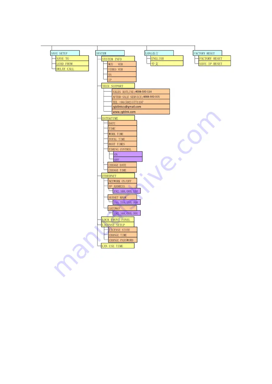
Page 54: ...gamma value Gamma values include 1 2 1 4 1 6 1 1 2 1 4 1 6 sRGB MENU TRANSITION Choose the TRANSITION press SEL to confirm then the LCD screen displays the level 2 menu as following MODE Switch mode...

Page 55: ...OM Bottom pop up PUSH BOTTOM Bottom push Note On behalf of the image emerging On behalf of the image disappearing Arrows represents the direction of the image move that is the image that arrow point i...

Page 56: ...age VOLUME Volume adjustment Note HDMI Can choose HMDI audio as INTERNAL embedded audio or EXTERNAL audio MENU SPLIT Choose the SPLIT press SEL to confirm then the LCD screen displays the level 2 menu...

Page 57: ...d to delay the input time MENU SYSTEM SYSTEM INFO System information MCU VER Information of MCU version VIDEO VER Information of VIDEO version SN It is the Factory serial number of VSP 516S which is u...

Page 58: ...ase button User can also press the two keys to unlock equipment LICENSE SETUP The device will not work if excess the prescribed time there are no signal output it needs to input password and modify th...

Page 59: ...provides detailed information about the control communication software The following topics are discussed Software Installation Software Operation How to Connect Upper Monitor by LAN Interface How to...

Page 60: ...ry easy to be configured with user friendly communication software support drag and drop operation for edit and display Also it can be customized with schedule function Double click to install English...

Page 61: ...5 Communication Software Guideline Software Installation VSP 516S User Manual 61 User can select Change to choose the VSP 516S install software...

Page 62: ...5 Communication Software Guideline Software Installation VSP 516S User Manual 62 Click Next to go on Click Next to go on...

Page 63: ...5 Communication Software Guideline Software Installation VSP 516S User Manual 63 Click Next to go on Click Finish and ready to run VSP 516S console...

Page 64: ...Connection When control video processor through PC software besides the power cord the product default equip with a line that is COM RS 232 9 pin DB9F RJ11 COM crystal head 6 B4C Below are the details...

Page 65: ...eft record serial interface name that computer provides as following chart the serial port is COM1 Confirm used COM and open control software click communication page enter setup option Serial is the...

Page 66: ...How to connect upper monitor by RS232 interface In addition we also equipped with USB line you can also connect the computer and video processor with it to control PC software Please refer to How to...

Page 67: ...ect with the net work If successful connect the icon becomes status on the left button showing Use File Toolbar Open script User can open saved script and alter its parameters Save script Save current...

Page 68: ...ion User can choose open device when start and using script saved before or execute schedule edited before when start If user choose open device when start user can use last run use script file or non...

Page 69: ...5 Communication Software Guideline Software Operation VSP 516S User Manual 69 Language The software supports Chinese English and German version The picture following is the English dialogue...

Page 70: ...tion Software Guideline Software Operation VSP 516S User Manual 70 The picture following is the German dialogue Exit Communication Toolbar Open COM Close COM Set COM Device Toolbar Synchronization Sav...

Page 71: ...e Factory setup Advance Note Audio patterns can choose audio input source for IMAGE A or IMAGE B Note VGA adjustment Same as MENU SAVE SETUP SAVE TO or the same as the SAVE key Same as MENU SAVE SETUP...

Page 72: ...Communication Software Guideline Software Operation VSP 516S User Manual 72 Note Same as MENU INPUT VGA ADJUST Schedule Toolbar Customize schedule Execute schedule Execute tasks according to schedule...

Page 73: ...n list VSP 516S has 20 output resolutions for users selection Note Images Display Mode Toolbar Choose to work in single channel or dual channel Note Layout Toolbar If in single channel mode the dialog...

Page 74: ...interface When user selects a dual channel mode select any channel image click on the toolbar interface the ICONS for the channel selection input interface i e SDI Composite1 Composite2 Composite3 S...

Page 75: ...on display picture can directly shows on corresponding screen Note Image Toolbar User can scale the images Image 2 can t choose in single channel mode Note Display Toolbar Display toolbar Users can se...

Page 76: ...ting Gamma is generally not recommended since LED large screen itself has Gamma function For further information users can contact with our customer service team Note Output Image Setup Toolbar User c...

Page 77: ...this area This process is sync to the parameters in images toolbars User Mode Toolbar Users can recall the saved user mode1 mode2 or mode3 Log Toolbar User can save or delete the operate log file Info...

Page 78: ...tware Operation VSP 516S User Manual 78 Split Split function choose ON can set H total V total H position V position H size and V size Note Same as MENU SPLIT Layout Through the layout of the user can...

Page 79: ...Users can setup up to 10 timing operation in the schedule IP Address Users can set equipment IP subnet mask and gateway usually used under the condition of one computer control or remote control sever...

Page 80: ...5 Communication Software Guideline Software Operation VSP 516S User Manual 80 Audio setting Help Options Version the update of software About the information of the software version and the company...

Page 81: ...nnect VSP 516S and computer with cable the connection diagram is as follows Power on VSP 516S start the network function specific steps are as follows MENU SYSTEM ETHERNET NERWORK select ON and check...

Page 82: ...nterface VSP 516S User Manual 82 Input IP address click OK Click to open the serial port check the if the Comm icon in the lower right corner of the control software interface is green and log outputs...

Page 83: ...the RJ11 download line to the RS232 on the video processor VSP 516S and the other side to be connected to the serial port on the PC There is no any serial port on your PC you will need another Serial...

Page 84: ...2 Interface VSP 516S User Manual 84 Click Device Manager on the left check the COM number as following COM1 is offered Remember the COM you are using and then run the control software find Communicati...

Page 85: ...er Set VSP 516S Boud Rate to be 115200 Click Confirm after setting Click open serial check if COM icon is on the bottom right corner when there is the prompt green showing on the software it means the...

Page 86: ...y USB Interface Install the driver Connect the USB cable to the PC and the video processor Turn on the VSP 516S for the first time to use USB the PC will remind finding the new hardware and ask to ins...

Page 87: ...Software Control Guide How to Connect Upper Monitor by USB Interface VSP 516S User Manual 87 When the installation finish can go to check the installed COM port inside the device management as followi...

Page 88: ...o Connect Upper Monitor by USB Interface VSP 516S User Manual 88 Install the console software and run after install shows the interface of the console as following Select the COM as installed just now...

Page 89: ...Interface VSP 516S User Manual 89 Press to start communication when there is green point in the right down corner showing on the software it means the communication is ok and you can use the software...

Page 90: ...t Resolution How to Realize Single Image Switching How to Set up the Size and Position of Signal Image How to Set up the PIP How to Choose the Signal Source in PIP How to Set up the Size and Position...

Page 91: ...t DVI I 18 Power supply port of Sending Card 33 DVI VGA DVI I Output 20 DVI input port of sending card 34 Switch and Power 21 Displayport Input 35 Power IEC 3 port 22 24 CVBS Input BNC port 32 DVI1 ha...

Page 92: ...1400x1050x60Hz 1440x900x60Hz 1600x1200x60Hz 1680x1050x60Hz 1920x1080x60Hz 1920x1080x50Hz 1920x1200x60Hz 2048x1152x60Hz 2560x812x60Hz 2560x816x60Hz In addition to CONT part and send card and power int...

Page 93: ...the video signal from HD player computer input signal via displayport interface SDI BNC Port Can receive video signal from HD player and HD camera connect interface 20 via 75 ohms BNC port Connect LE...

Page 94: ...of Sending Card 27 Audio Output 10 15 DVI input port of sending card 28 DVI Output DVI I 16 Switch 29 DVI VGA DVI I Output 17 Displayport Input 30 Power IEC 3 port 28 DVI1 have default the main image...

Page 95: ...1440x900x60Hz 1600x1200x60Hz 1680x1050x60Hz 1920x1080x60Hz 1920x1080x50Hz 1920x1200x60Hz 2048x1152x60Hz 2560x812x60Hz 2560x816x60Hz In addition to CONT part and send card and power interface outside o...

Page 96: ...l from HD player computer input signal via displayport interface SDI BNC Port Can receive video signal from HD player and HD camera connect interface 20 via 75 ohms BNC port Connect LED screens via ne...

Page 97: ...ce is in Normal Operation 1 Firstly make sure the power of device setup 2 After power on the fans running the button scanning 3 After the button scanned the device operate the LCD display that RGBLINK...

Page 98: ...into the circulation state circulation process indicates that the current input signal source the current output format the current program version information the current equipment serial number the...

Page 99: ...tton enter menu option 2 Press UP DOWN button choose LANG option 3 Press SEL button change the status of option to 4 Press UP DOWN button or LEFT RIGHT button change the default ENGLISH to Chinese 5 A...

Page 100: ...olution 1 Press OUT button enter output format option 2 Press UP DOWN button or LEFT RIGHT button choose the required resolution for example 2048x1152x60 3 Press SEL button finish the choice of resolu...

Page 101: ...other source such as DVI direct light touch DVI key LCD screen display as follows Choose DVI buttons button lamp CV1 destroy and DVI key light and shining can realize single picture of input signal so...

Page 102: ...tion 2 Press UP DOWN button choose the OUTPUT option 3 Press SEL button press UP DOWN button choose SCALE option 4 Press SEL button enter SCALE option through UP DOWN button after finished press SEL c...

Page 103: ...ual 103 How to Set up the PIP Boot the system default for single image output if users need to set to double picture the light touch I II key LCD screen display as follows PIP option is ON open the PI...

Page 104: ...hosen as the main channel for example choose the CV2 3 Press AB button the key lighting choose the sub image signal source press the CV1 CV2 CV3 SVID DVI YPbPr VGA SDI directly as the sub main channel...

Page 105: ...on through UP DOWN button choose OUTPUT choose SCALE According to user needs can pair respectively picture image size and position are set 3 After completion of the setting of the Sprite again light t...

Page 106: ...6 System Setup and Operation How to Set up the Size and Position of PIP VSP 516S User Manual 106 4 Through the above steps can complete the master picture image size and position setting...

Page 107: ...107 How to Set up the Layout of PIP 1 Under PIP mode press I II button 2 Through UP DOWN button choose LAYOUT option press SEL to confirm 3 Through UP DOWN button Choose three PIP LAYOUT effects were...

Page 108: ...UP DOWN button choose OUTPUT choose SCREEN option 2 According to user needs can be shown on the screen size and position are Settings 3 SCREEN setup is completed in the SCREEN MODE to choose the optio...

Page 109: ...the Brightness Adjusting 1 Press MENU button though UP DOWN button choose INTPUT to enter 2 Through UP DOWN button enter BRIGHTNESS option press SEL button to confirm through UP DOWN button to adjust...

Page 110: ...eze and Live Image Switching 1 Press FRE button freeze the current live image 2 Press FRE button again the current freeze image is switched live image Note Can choose FREEZE IMAGE or LIVE VIDEO via ME...

Page 111: ...size of the audio volume value such as can turn it down to 20 Note Same as MENU AUDIO MUTE ON OFF Note The or button can also adjust the value 4 Under the PIP mode first of all should choose audio inp...

Page 112: ...automatically in appointed time and operation of single or dual channels also can set up the ratio and position Users can setup up to 10 timing operation in the schedule 1 First make sure the VSP 516S...

Page 113: ...timing play appoint Time The time timing play appoint Operating Mode User can choose single or dual channels Scale User can set the image ratio and position for Image 1 and Image 2 Dual channels Auto...

Page 114: ...6 System Setup and Operation How to Set Up the Playlist VSP 516S User Manual 114 7 The software default Device Schedule function close user should click on icon to realize automatically play...

Page 115: ...e out the edit operation inconvenience VSP 516S provides three save preferences 1 Press SAVE button the key lights the SAVE function open 2 SAVE1 SAVE2 SAVE3 all light 3 Select the location of the nee...

Page 116: ...eration inconvenience VSP 516S provides three save preferences 1 Press MENU button 2 Through UP DOWN button choose SAVE SETUP option 3 Press SEL button through UP DOWN button again choose LOAD FROM op...

Page 117: ...teps are as follows 1 Connection and Setting 1 Connect the DVI signal to DVI interface of the two VSP 516S through DVI distributor DXP 0108 2 Divide the LED display into two parts respectively for 115...

Page 118: ...et the screen width H SIZE for 1152 The screen width of VSP 516S Set the screen height V SIZE for 1024 The screen height of VSP 516S Set the horizontal position H POS for 0 The horizontal position of...

Page 119: ...osition of VSP 516S that is horizontal split so the vertical value is unchanged 3 Save Press SAVE button the key lights start the SAVE function And SAVE1 SAVE2 SAVE3 all light Select the location that...

Page 120: ...6 System Setup and Operation How to Achieve Multiple Cascade VSP 516S User Manual 120...

Page 121: ...opics are provided No Output in LED Display Flash Point in LED Display Output LED Display only Shows Part of the Image No Display in the Second Half Part of LED Display Left Screen Appears Two Black S...

Page 122: ...whether the signal is correct on the monitor If not display properly please check whether there is input signal or if input wire interface is taken tight output wire interface is picked up tightly If...

Page 123: ...on to be bigger than screen width by button MENU under OUTPUT RES and touch knob to confirm Sending Card Can not Take Lower Part TS 802 can control the max horizontal resolution 2048 and vertical reso...

Page 124: ...e VSP 516S may appear color abnormal when input SDI signal it needs adjust the SDI input setting specific operations are as follows Press MENU key and select INPUT option select SDI ADJUST through UP...

Page 125: ...Can Connect DVI or HDMI Signal DP Port Can Only Connect DP Signal DP port can only connect DP signal please choose graphics card with DP output port If need 2 DVI or HDMI you can choose HDMI to DP SDI...

Page 126: ...80i50 1080i60 VGA DB15 Input Number of Inputs 1 Connector Standard DB15 Socket Supported Standard VGA UXGA Signal Level R G B Hsync Vsync 0 to1Vpp 3dB 0 7V Video 0 3v Sync 75 ohm black level 300mV Syn...

Page 127: ...umber of Outputs 2 Connector Standard DVI I Socket Signal Level TMDS pw 165MHz bandwidth Supported Resolution VESA 800 600 60Hz 1024 768 60Hz 1024 768 75Hz 1280 720 60Hz 1280 720 50Hz 1280 768 60Hz 12...

Page 128: ...bps 24bit Function Input channel configuration Support each input channel signal programming configuration PIP Support PIP PBP for any two inputs Audio sync switch support Extras Communication RS232 U...

Page 129: ...e owner Warranty related repairs include parts and labor but do not include faults resulting from user negligence special modification lighting strikes abuse drop crush and or other unusual damages Th...

Page 130: ...oad line to the RS232 on the video processor and the other side being connected to the serial port on the PC Double click to run flash magic setting as below Firstly users can choose the right serial...

Page 131: ...ad exit the program turn off the power tack the two coding switch back as below restart the equipment power check if the equipment work normally Note Flash Magic download website http www flashmagicto...

Page 132: ...t confirm if it is consistent with the computer such as 192 168 0 take 192 168 0 100 for example 3 Open the webpage input IP 192 168 0 100 this is the default state if the IP address is changed the IP...

Page 133: ...s LCD screen it means it s in loading program status 7 If display UPDATE SUCCESS PLEASE RESTART Or display Video Fireware Update Success on webpage it means the program is loaded successfully otherwi...

Page 134: ...VSP 516S User Manual 134 8 Restart the device and check the running state then end the mainboard program update...

Page 135: ...e as follows 1 Opening the Processor 2 Installing an Optional SDI Input Board 3 Closing the Processor Part 1 Open the Processor Specific steps are as follows 1 Disconnect the AC power cord from the VS...

Page 136: ...wrist strap is recommended 6 Perform the desired maintenance procedure See Installing an Optional SDI Input Board in Part 2 Part 2 Installing an Optional SDI Input Board Install an optional SDI input...

Page 137: ...VSP 516S User Manual 137 Figure 3...

Page 138: ...Figure 4 4 Close and reinstall the processor see Closing the Processor in Part 3 Part 3 Closing the Processor Specific steps are as follows 1 Secure the back panel with the screws 2 Replace the top c...

Reviews: