background image

©

Xiamen RGBlink Science & Technology Co., Ltd.

Ph: +86 0592 5771197 | [email protected] | www.rgblink.com

28

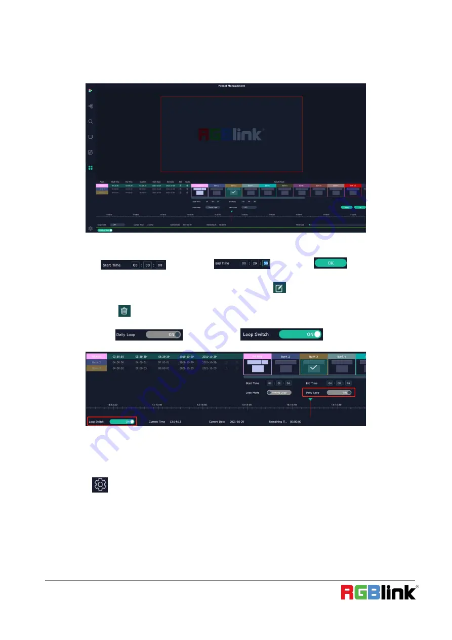
Schedule Mode

This mode is designed to set auto bank (scene/preset) switch.

1.Select the bank that need to be looped.

2.Set

Start Time

and

End Time

and click

OK

to confirm.

The Preset can be added into the loop list after confirm. click this icon

to edit Start Time and End Time if

needed.Click this icon

to delete this preset if it is not needed.

3.Turn on

Daily Loop

and

Loop Switch

.

System Setting

Click this icon

and enter System Setting interface

Summary of Contents for VENUS X8K LEGENDARY

Page 1: ... UHD layers per port Fully customisable in out resolutions EDID Management OSD overlay features XPOSE 2 0 Web Server Built in with IP connection Genlock Sync I O Module Based Design and hot swap capacity Each input module support up to 4 4K2K 60 Each output module support up to 2 4K2K 60 ...

Page 2: ...2 Overview 3 Packing Configuration 4 Hardware Orientation 5 Front Panel 5 Rear Panel 6 Install Your Product 7 Plug in Signals 7 Plug in Main Power 7 Turn on Your Product 7 Use Your Product 7 Install XPOSE 2 0 8 Layer Management 20 Preset Management 24 System Setting 28 Web Server Control X8 32 Contact Information 33 ...

Page 3: ... features RGBlink 3rd generation high performance video scaling technology for excellent image reproduction The most outstanding feature of it is its throughly modular design the card frame style SmartSlot system allowing installation of up to 24 inputs and 12 outputs Any input can be scaled positioned routed transcoded to any output or be assembled as layers across outputs Built for intensive swi...

Page 4: ... Science Technology Co Ltd Ph 86 0592 5771197 support rgblink com www rgblink com 4 AC Power Cord Packing Configuration Note AC Power Cable supplied as standard according to destination market Network Cable HDMI Cable ...

Page 5: ...Ph 86 0592 5771197 support rgblink com www rgblink com 5 Hardware Orientation Front Panel Front Panel Structure 1 TFT LCD panel show the info of input and output module device status weather and so on 2 1 USB 2 0 1 USB 3 0 blue for upgrade 2 1 ...

Page 6: ... SDI Input Module Single HDMI 2 1 DP 1 4 Output Module 2 6 output module slots up to 12 outputs totally for Dual 4K HDMI Output Module Dual DP 1 2 Output Module 3 Communication ports including Genlock LAN RS232 CTL USB 3 0 and HDMI 4 CXP ports to be developed 5 2 slots for power supply modules and Power Switch HDMI 2 1 DP 1 4 Input Module Leadtime 2022 6 1 DP 1 2 Input Module Leadtime 2022 6 15 DP...

Page 7: ... connect LAN port of device and computer with network cable or connect both device and computer to the same router make sure their IP address is not completely same Plug in Main Power Connect IEC cable to device and plug into wall socket Turn on power at wall socket If the devices is restarted make sure the indicator light upon the PSU module is totally out before plugging in the power Turn on You...

Page 8: ...isplay normally if the resolution is lower than 1920x1080 Operating system Windows 7 or above full version not Ghost version or compact version CPU i5 and above Mac Monitor Resolution must be 1680x1050 pixel or above it can not display normally if the resolution is lower than 1680x1050 CPU i5 and above XPOSE Controls X8 Connect the Device Click the icon to open System Setting and select X8 in Find...

Page 9: ...9 purple tip indicates input modules blue output modules yellow communication port Input Setting Click any input port in purple area the board where the port locates is selected Users can do settings to the board now A red rectangle flashes around the chosen port when it is clicked Property Setting ...

Page 10: ...Height Vertical and horizontal size Crop Left crop left Top crop top Width horizontal size after crop Height vertical size after crop SDR to HDR Status ON OFF Gamma 0 9 99 Adjust the brightness of picture the higher the number the higher the brightness Bright Factor 0 9 99 EDID Setting Input Port Current Port and type Customized EDID Monitor Name Width Height and Frequency ...

Page 11: ...lide to On or OFF Format Range select ALL or Module All means this setting is applied to all output ports Module means this setting is only valid on this module Format Type Standard Customize Choose Customize width Height Refresh Rate have to be put in by users manually Format when format type is Standard there are standard format list to choose Format for ALL 720 480 60i 到 7680 1080 60 Format for...

Page 12: ...position Width Height the horizontal and vertical size of the text Font Style Font font of the text all fonts installed in the computer is available Font Type Normal Italic Bold Bold Italic Font size 0 300 pixels Pixel alignment Left Right Center to Horizontal Vertical Center Right Align Bottom Right Align left bottom Vertical center left Vertical center Horizontal center bottom Transparent font t...

Page 13: ... 0 16 Scroll Direction Scroll Off Scroll Left Scroll Right Input Text The exact content of the text After setting users choose Save OSD Clear OSD if the setting is not desired or Close All OSD Device Overview Click Return there are overview IP setting Fan Control Power ON Factory Setting Overview show Device Info module info of version and temperature in each slot IP Setting Select Auto IP address...

Page 14: ...trol Auto adjustment ON OFF Fan speed 0 100 Backup Backup ON OFF Backup Mode Input Backup Preset Backup Power On Reserve Power On Reserve 0 255s Factory Setting Remove Logo EDID Save IP Display Management Display System is for users to set layout of outputs Click this icon first enter the interface as follow ...

Page 15: ...There are 15 types of basic Display Area which is used to contain output interface and could be regarded as layout of output Mode At present X8 supports Presentation Mode Other products of X series also support PST PGM Mode Rotation Mode and Edge Blending Rotation and Edge blending is valid only when ARO rotation module is installed to the device Each mode is marked in different color and provided...

Page 16: ...agged from Template under Presentation Mode Delete Container long press the to cancel the Container Display Area Customize Container Click this icon at the bottom of template list fill in the H Total V Total Row and Column then click a customized containers is created If this container need to be saved click SAVE ...

Page 17: ... com 17 For example create a 1 2 7680 2160 container as follows Adjust Display Area Place the mouse in the Container roll the mouse can zoom in or out the Container in the XPOSE window Clicking icon and can do the same work Drag the border of the display area to move its place in the interface ...

Page 18: ...is dragged into container meaning this output is used and the output port get dark Click this icon on Display to cancel the display in Display Area Pressing CTRL ALT can lead to close of all displays on the XPOSE window Display System Show all Containers Display Area that have been created Click tick icon behind to give alias to the each Display Area if necessary ...

Page 19: ...k com www rgblink com 19 Parameters Parameter is designed to set size Width Height and position X Y of each display There are two ways to adjust the display by Parameter or by the bar below the window Parameter Bar under XPOSE window Swap Swap two output ports if needed Hotkey ...

Page 20: ...www rgblink com 20 Layer Management Layer Management is designed to manage the layer of each monitor Click this icon to enter the interface Display Area Here is to show all the Display Area set in previous step System Management Click to cancel or use the corresponding Display Area ...

Page 21: ...confirm the alias setting Layer After signal is dragged into display show Layer index Versus Signal index Numbers on Monitor Numbers on monitor is to show how many layers at present allowed to put in the monitor each neighboring monitor 5 and 6 9 and 10 allows to put 8 layers if there is no neighboring monitor in the display area the single monitor can contain 8 layers For example in one display a...

Page 22: ... to adjust layer 1 Use the bar under the interface Choose one layer and the bar shows its signal source type in position and size 2 Layer Scale and Crop Alpha 0 128 Brightness Contrast Saturation 0 100 Freeze Turn ON freeze to prevent misoperation Layer Movement Place the cursor on the layer it turns to a palm icon press the left of mouse the icon turns to a fist moving the mouse can drag the laye...

Page 23: ...tors in the same Display Area with the one signal as the following Layer Lock Click the lock icon on the right middle of the later boarder When the layer is locked any movement or removal to the layer is invalid Other Operation on Layer Use the tools bar on top of window to do such operations Layer Backward Layer Forward Layer to Bottom Layer to Top Select All Copy Selected Paste Selected Cancel S...

Page 24: ...NK is done click next or other BANK this BANK can be saved automatically Blending Width the width of blending Turn ON blending HotKeys Hot keys provided to do quick layer setting such as Copy Layer Layer move Preset Management Preset Management is designed to switch bank scene setting done in last step Preset Management Mode 1 Manual Mode 2 Schedule Mode ...

Page 25: ...ch Manual Mode or Schedule Module by the bar in the left bottom corner of the window Preset is showing the BANK selected PGM is in first box in the bottom left Take Setting Click this icon after selecting a BANK Fade Time 0 0 10 0S Black out slide to ON or OFF The tick on the bank indicates that the bank is selected ...

Page 26: ... effect Take switch from PST to PGM with chosen effect in set Fade Time Display Area Display Area is to let users to choose which display areas to display on the PGM and allow users to set transition effect for each display area so that they can switch from PST to PGM in desired effect Bank Save and Load Save Bank to Page Select a bank click Page select Page X the bank is saved in the page The pag...

Page 27: ...script is saved the bank name will appear in the load list Select the file and click Load Select the file and click Delete the chose file can be deleted from list Preset Name Select a bank and click Preset Name fill in the blank after New Preset Name to rename a Preset Bank Click the color block after Color Selection and choose a new color for the boarder of chosen bank For example change Bank1to ...

Page 28: ...h 1 Select the bank that need to be looped 2 Set Start Time and End Time and click OK to confirm The Preset can be added into the loop list after confirm click this icon to edit Start Time and End Time if needed Click this icon to delete this preset if it is not needed 3 Turn on Daily Loop and Loop Switch System Setting Click this icon and enter System Setting interface ...

Page 29: ...ssian Keyboard Manager click keyboard it will redirected to keyboard setting window Keyboard setting is designed to fit for different operation systems such as Windows and Mac Users can set short cut keys for Input Output Layer and Preset Drag Input Output Layer and Preset from the list to the keys you desired as follow Please note the keyboard area where allows to set short cut keys as follow ...

Page 30: ...ve all already set short cut keys After setting the shortcut keys you can modify the default file name and save the script The script will be automatically saved to the corresponding path in the XPOSE folder You can load in script Settings when used again Find Device New version of XPOSE 2 0 is blank default in Find Device Users are supposed to choose the device needed in System Setting Communicat...

Page 31: ... and putting its IP Address Authorization Setting Click to open up the authorization entry Click Management New Add new USER NAME and PASSWORD Edit Edit user name and password already built Delete Delete user name and password already built Permission functions on this XPOSE 2 0 on this computer that the created users are allowed to operate ...

Page 32: ...o back up operation from current running device to this device slave unit shall be used First fill in the quantity of to be linked devices click Set Numbers Index Device IP and State will come up Choose the IP address of the other device from drop down list e g IP192 168 0 45 and Slide to ON the red dot behind turns to green indicating that the device has been connected Web Server Control X8 X8 su...

Page 33: ...k warranties are only valid to the original purchase owner Warranty related repairs include parts and labor but do not include faults resulting from user negligence special modification lighting strikes abuse drop crush and or other unusual damages The customer shall pay shipping charges when unit is returned for repair Headquarter S601 Weiye Building Torch Hi Tech Industrial Development Zone Xiam...

Reviews: