19.7
EXTERNAL POWER AMP I/O MODULE
EXT POWER AMP
1
2
3
4
+
-
1
2
EXT MTR
AMP FAIL
+
-
+
-
EXTERNAL POWER AMP
FAIL INPUT #1
EXTERNAL POWER AMP
FAIL INPUT #2
TO EXTERNAL
RECEIVE LEVEL
METER
TX
RX
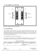
Figure 19-18. External Power Amp I/O module, rear panel view
19.7.1
DESCRIPTION
The external power amp I/O provides an interface when an external high power amplifier is used with the 9785.
This module replaces the standard 10W power amplifier for this application. Two panel mounted BNC
connectors provide the TX and RX signal interface for the external amplifier and receiver connection.
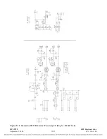
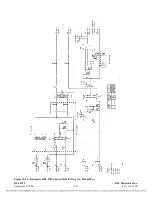
The External Power Amp I/O module (Figure 19-18) is composed of two sections. One section provides an RX
line interface and has provisions for an external power meter, and the other section provides TX scaling and
external power amplifier fail inputs. This I/O module is presently available in the following version:
Alarm Input Voltage
Assembly No.
12V or 48/125V
106675-1
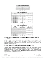
This module has six sets of jumpers that must be configured before the module is placed in service.
The B board has jumper JP101 which can select three RX terminations (50
Ω
, 75
Ω
, or high
impedance). The A board has five sets of jumpers: JP1, JP2, JP3, JP4 and JP5. Jumpers JP3 and JP4
must be set to position C to select 12V alarm inputs, or position B to select 48/125V inputs. Setting
jumpers JP1, JP2 and JP5 are described in Tables 19-7 and 19-8.
The Input/Alarm I/O module is primarily used for TX/TX, TX/RX or TX only applications, which use
an external 50W or 100W power amplifier. It can also be used for customer specific applications and
can be mounted in a spare I/O slot or in an expansion chassis.
RFL 9785
RFL Electronics Inc.
September 1, 2006
19-32
(973) 334-3100


