11.2
SPECIFICATIONS
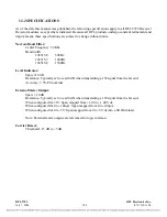
As of the date this manual was published, the following specifications apply to all RFL 9785 Receiver
Downshifter modules. Because all RFL products undergo constant refinement and improvement, these
specifications are subject to change without notice.
Frequency Range:
30 kHz to 535 kHz, frequency is adjustable in 250 Hz steps.
Modulation:
AM.
Bandwidth:
3700
Hz.
Input Attenuation:
0dB to 50dB in 10dB steps.
Gain Adjust:
4dB to 40dB.
Output Impedance:
100 ohms.
Output Signal:
24 kHz baseband.
11.3
THEORY OF OPERATION
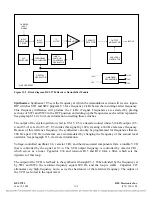
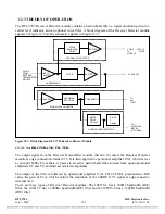
The main function of the RFL 9785 Receiver Downshifter Module is to convert the incoming signals
to a 24 kHz base frequency (bf). Basically, the RFL 9785 Receiver Downshifter performs the
frequency conversion by first up-converting the signal to 5.12 mHz, by using a programmable
synthesized local oscillator. The signal is then fed to a crystal filter that passes the lower 3700 Hz wide
sideband of the 5.12 mHz signal.
Next, the signal is down-converted to a 2 kHz carrier, and then to the 24 kHz bf. The bf signal is
passed on to the RFL 9785 Filter Module (Section 9) for further processing.
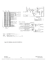
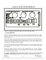
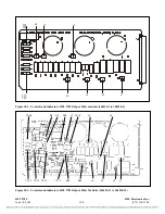
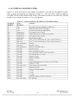
A block diagram of the RFL 9785 Receiver Downshifter appears in Figure 11-2, controls and
indicators appear in Figure 11-3, a component locator drawing appears in Figure 11-4, and a schematic
diagram appears in Figure 11-5.
Crystal Oscillator .
Transistor Q1, crystal Y1, varactor CR2, and their associated components form a
crystal oscillator. This oscillator serves as the beat frequency oscillator (BFO) for the product detector,
as well as the frequency reference for the frequency synthesizer. The voltage applied to the cathode of
CR2 determines the output frequency of the crystal oscillator. FREQ ADJ potentiometer R15 is used to
adjust this voltage for an output frequency of 5.12 mHz.
RFL 9785
RFL Electronics Inc.
June 18, 2009
11-2
(973) 334-3100


