


RF-43UH
Shenzhen RF-star Technology Co., Ltd.
Page 6 of 35
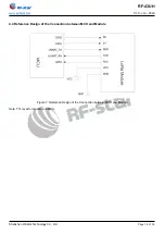
Figure 7. Reference Design of the Connection between MCU and Module
.................................... 14
Figure 8. Transparent Transmission Function Diagram
........................................................................... 19
Figure 9. Point Transmission Function Diagram
......................................................................................... 20
Figure 10. EN Timing Diagram of Wake-up Sleep MCU
.......................................................................... 21
Figure 11. EN Timing Diagram during Sending Data
................................................................................ 21
Figure 12. EN Timing Diagram during Receiving Data
............................................................................. 22
Figure 13. EN Timing Diagram during Setting Data
................................................................................... 22
Figure 14. Recommended Reflow for Lead Free Solder
......................................................................... 33
Figure 15. Optional Packaging Mode
Table of Tables
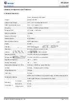
Table 1. Parameters of RF-43UH
Table 2. Pin Functions of RF-43UH
Table 3. Recommended Operating Conditions of RF-43UH
.................................................................. 10
Table 4. Handling Ratings of RF-43UH
Table 5. Current Consumption of RF-43UH
Table 6. Temperature Table of Soldering and Reflow
................................................................................ 32