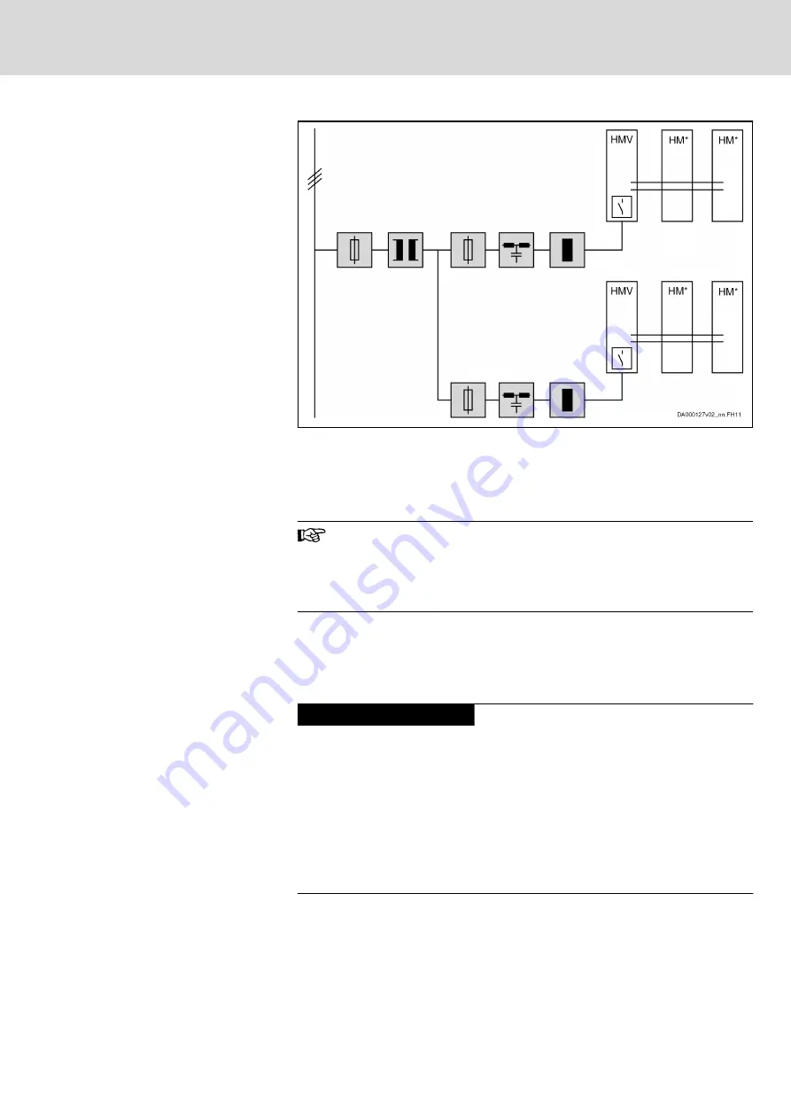
HMVxx.xE
Components marked with gray background color: Optional, depending
on the application
HMVxx.xR
Mains filter and mains choke: necessary
HMVxx.xR-
W0120
Mains filter, mains choke, external mains contactor: necessary
Fig.8-2:
Group Supply HMV Without DC bus Connection of the Groups
When dimensioning the fuses in the supply feeder and in branch‐
es, make sure to provide protection against overcurrent and over‐
load in the case of error.
See
chapter 15.3.5 "Dimensioning the Line Cross Sections and
Notes on Project Planning
The maximum allowed number of devices at the common DC bus is limited
by the ability of HMV to charge capacitances against housing (C
y
).
Use more HMVs, if the determined capacitance C
y
exceeds the maximum al‐
lowed value.
Damage to the supply unit!
NOTICE
Do not exceed allowed peak and continuous powers in the DC bus.
Comply with minimum value of mean phase control factor ā (see data of con‐
tinuous power of supply unit in the technical data, calculation see chapter
), in order to avoid overload of the integrated DC
bus capacitors by wattless currents.
High load due to wattless current is generated, when, for example, synchro‐
nous motors permanently deliver high torque at low speed or asynchronous
motors are operated with high magnetization currents.
In these cases of operation, use additional capacitances at the DC bus.
Smart Energy Mode
Regenerative supply units of the HMV0x.1R-W0***-A-07-FNN2 design (Smart
Energy Mode) reduce current and power peaks on the mains side. The Smart
Energy Mode limits the maximum device current to the 1.1‑fold value of the
nominal current.
DOK-INDRV*-SYSTEM*****-PR06-EN-P
Rexroth IndraDrive Drive Systems with HMV01/02 HMS01/02, HMD01, HCS02/03
Bosch Rexroth AG
97/309
Configuring the Drive System


