15.1.3
DC Bus Peak Power
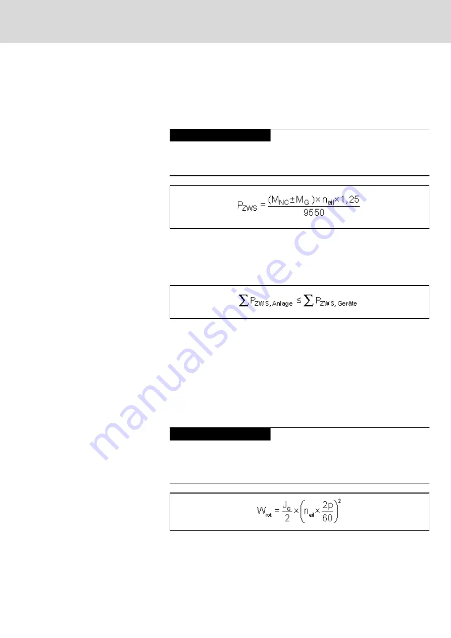
The drive controller or combination of drive controllers has to produce DC
bus peak power for example when several axes of a machine tool simultane‐
ously accelerate to rapid traverse rate after a tool change, approaching the
workpiece.
Damage due to supply unit overload!
NOTICE
To avoid damage to the drive controller, the sum of peak powers of all drives
mustn't exceed the DC bus peak power of the supplying drive controller (cen‐
tral supply).
M
NC
Acceleration torque in the drive [Nm]
M
G
Torque due to weight for vertical axes [Nm]
n
eil
Speed at rapid traverse rate [min
-1
]
P
ZWS
DC bus peak power [kW]
1,25
Constant for motor and controller efficiency
Fig.15-12:
DC Bus Peak Power per Drive
P
ZWS,Anlage
Generated DC bus peak power of the installation
P
ZWS,Geräte
Allowed DC bus peak power of the devices
Fig.15-13:
Supply Condition: DC Bus Peak Power
15.1.4
Regenerative Power
When all main and servo drives connected to a drive controller or combina‐
tion of drive controllers brake simultaneously, the generated regenerative
power must not be greater than the maximum regenerative power of the drive
controller or combination of drive controllers. If this is not taken into consider‐
ation in sizing the system, thermal destruction of the braking resistors in the
drive controllers may occur.
Destruction due to braking resistor overload!
NOTICE
Do the project planning for drive controllers or combinations of drive control‐
lers in such a way that the resulting regenerative power can be absorbed
when all main and servo drives connected to the drive controller or combina‐
tion of drive controllers brake simultaneously.
W
rot
Rotary energy [Ws]
n
eil
Speed at rapid traverse rate [min
-1
]
J
G
Motor inertia and load inertia reduced to the motor shaft [kgm²]
Fig.15-14:
Regenerative Power per Drive
DOK-INDRV*-SYSTEM*****-PR06-EN-P
Rexroth IndraDrive Drive Systems with HMV01/02 HMS01/02, HMD01, HCS02/03
Bosch Rexroth AG
251/309
Calculations


