


6-18
Electrical Data
Rexroth IndraDrive C
DOK-INDRV*-HCS02.1****-PR02-EN-P
6.8 Control
Voltage
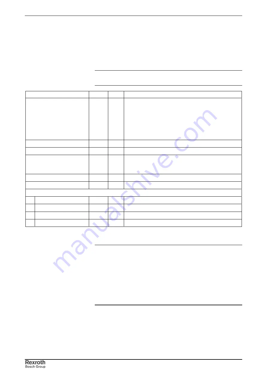
Devices without Internal Control Voltage Supply (HCS02.1E-W00xx-
NNNN)
Note:
The data below apply to the control sections.
The data are referring to an ambient temperature of 25 °C.
Designation
Symbol
Unit
Value
control voltage
U
N3
V
•
24
±
20%
(when no motor holding brake is used)
•
If motor holding brakes are to be supplied, observe the
data of the motor documentation. The following values are
normally sufficient:
24
±
5% with motor cable length <50 m
26
±
5%
with motor cable length
>50 m
max. ripple content
w
-
mustn't exceed the control voltage range
max. allowed overvoltage
U
N3max
V
33 (max. 1 ms)
max. charging current
I
EIN3
A
2.8
plus charging current of control section (see Project Panning
Manual IndraDrive Control Sections)
max. pulse duration of I
EIN3
t
EIN3Lade
ms
15
max. input capacity
C
N3
mF
1.2 * 0.47
power consumption:
HCS02.1E-W0012
P
N3
W
12
HCS02.1E-W0028
P
N3
W
14
HCS02.1E-W0054
P
N3
W
23
HCS02.1E-W0070
P
N3
W
23
* data without motor holding brake and control section CS* taken into account
Fig. 6-18:
Control voltage
Note:
Overvoltages of more than 33 V have to be derived by
measures in the electrical equipment of the machine or
installation. This includes:
•
24-Volt mains sections that reduce incoming overvoltages
to the allowed value.
•
Overvoltage limiters at the control cabinet input that limit
existing overvoltages to the allowed value. This also
applies to long 24-Volt lines that have been laid in parallel
with power and mains cables and can absorb overvoltages
caused by inductive or capacitive coupling.


