9
Smart Condition Monitoring System Electrical and Communications Manual
Transducer Connection
CONNECTING YOUR OWN 4-20MA CURRENT
TRANSDUCER
It is very important that you do not connect the cable from
the 4-20mA source to the converter box without
successfully completing this procedure. If it is not possible
to successfully complete this procedure, then the cable
should be left disconnected and adequate protection to
prevent shorting of the wires or dirt contamination be
provided until such a time as a test can be completed.
1. To complete this test, the cable from your 4-20mA CT or
PLC providing the signal must be disconnected and
isolated at the source.
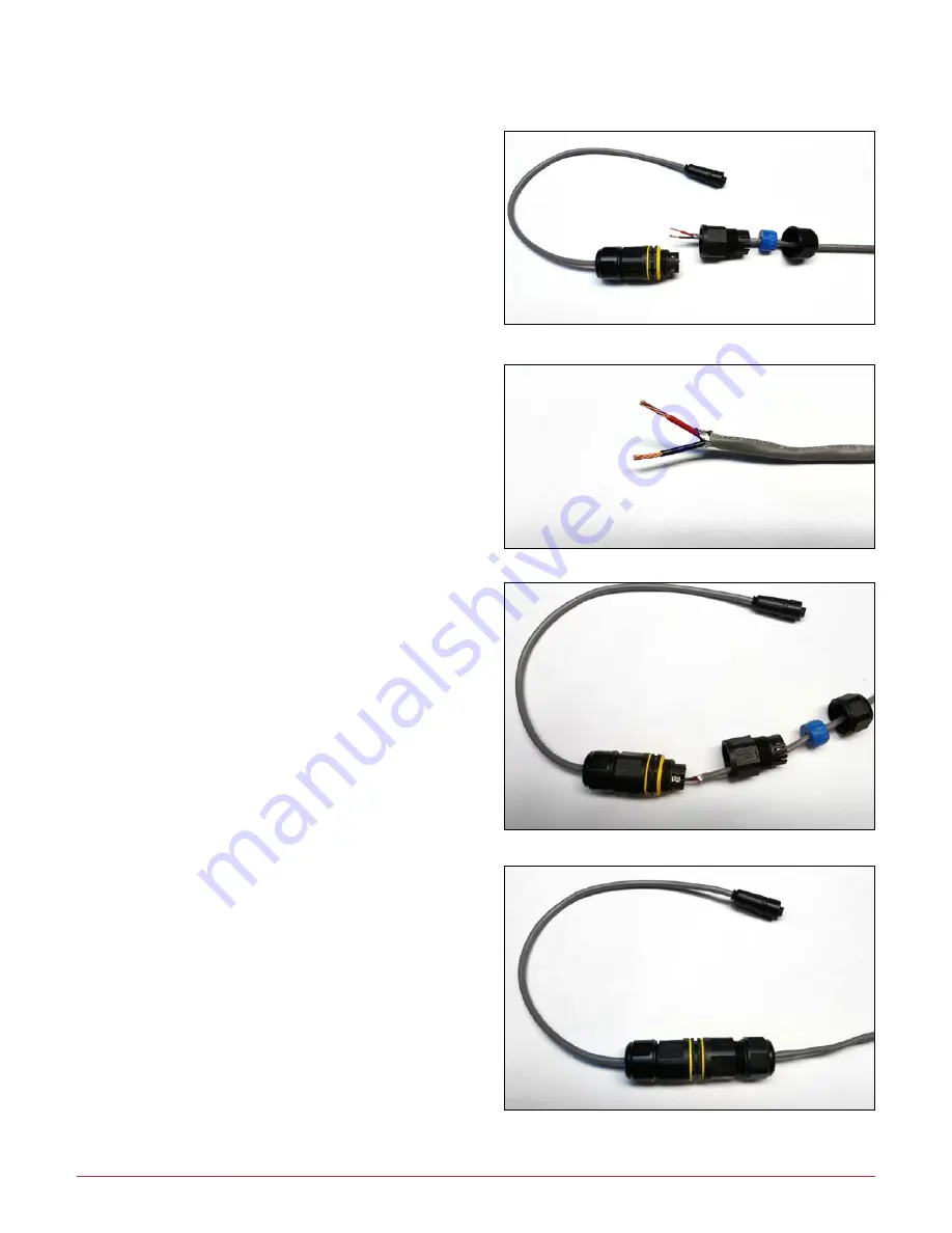
2. Please provide a 2-core cable. Verify it has been
disconnected from the signal source at the other end.
Ensure the LCVC8001 converter box connector is not
connected to either the converter box or the Loop
Current Polarity Checker box. Unscrew the free end of
the cable joint, and slip the gland nut, seal grommet, and
removable terminal cover up the cable (
Step A
).
3. Strip back the cable jacket 1” and strip each of the 2 core
wires back ½” to bare wire (
Step B
).
4. There are only 2 screw down terminals inside the cable
joint. Loosen, insert a bared core wire and tighten the
terminal and repeat. It is not important at this stage
which core wire is connected to which terminal (
Step C
).
5. Screw terminal cover onto cable joint, slide down blue
cable gland seal and insert into “fingers” then slide down
gland nut and loosely tighten (
Step D
).
6. Connect the 4-20mA CT or PLC cable at the source end
and connect the Polarity Test Box to the EN2 connector
on the end of the lead from the cable joint by slowly
turning the connector until the key aligns then insert and
tighten the finger lock nut on the connector. Sometimes
the finger nut needs to be turned slightly to allow the
connector to engage fully (
Step E
on the following page).
7. Provide either a test signal from the PLC or engage the
equipment such that current is drawn by the motor.
Using a Multimeter with the input and range set to
around 0-20V dc (0-10V dc minimum) check whether a
positive or negative voltage reading is shown on the
multimeter (
Step E
). Note that even if the motor is not
turning, the meter should read 1V dc or -1V dc.
Step A
Step B
Step C
Step D


