background image


Packaging, Transport and Installation 


14 


3.4  Conditions for the Installation Site 


NOTICE


N7.0021


Ambient temperature 

Temperatures outside the permitted range 

  Electronic and mechanical components may be damaged. 

  The performance data alter to an unknown extent. 


Do not exceed or fall below the permitted temperature range (5 °C to 
40 °C ambient temperature) of the device.


  Installation height: max. 2

 000 m above sea level 


  Ambient temperature: 5 °C 

– 40 °C 


  Maximum relative humidity < 80 % (at ambient temperatures 

≤ 31 °C) 

 
For ambient temperatures U

T

 between 31 °C and 40 °C, the maximum relative humidity value L

F


linearly decreases according to L

F

 = 

–(U

T


– 55) / 0.3: 

Ambient temperature 

Max. rel. humidity 

≤ 31 °C 

80 % 

33 °C 

73.3 % 

35 °C 

66.7 % 

37 °C 

60 % 

39 °C 

53.3 % 

40 °C 

50 % 


NOTICE


N8.0015


Humidity 

High relative humidity 

  Electronic and mechanical components may be damaged. 

  The performance data alter to an unknown extent. 


The relative humidity in the vicinity of the device should be kept as 
low as possible.


Summary of Contents for PT 300

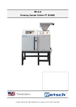
Page 1: ... Retsch GmbH 42781 Haan Retsch Allee 1 5 Germany 27 10 2020 Version 0002 Manual Rotating Sample Divider PT 300 600 Translation ...

Page 2: ...2 Copyright Copyright by Retsch GmbH Retsch Allee 1 5 42781 Haan Germany ...

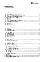
Page 3: ...e 18 4 2 Divider modules 19 4 3 Feed size 19 4 4 Rated Power 19 4 5 Motor Rotation Speed 19 4 6 Emissions 20 4 6 1 Noise levels 20 4 7 Degree of Protection 20 4 8 Protective Equipment 20 4 9 Dimensions and Weight 20 4 10 Required Floor Space 20 4 11 Installation drawing 21 5 Views of the device 23 5 1 Front view 23 5 2 Interior view 24 5 3 Operating elements and displays 25 6 Operating the device ...

Page 4: ...4 10 Disposal 37 11 Index 39 ...

Page 5: ...Notes on the manual 5 ...

Page 6: ...rnings in this manual No liability will be assumed for damage to property resulting from the failure to follow the information in this manual 1 2 Copyright This document or parts of it or its content may not be reproduced distributed edited or copied in any form without prior written permission of Retsch GmbH Damage claims shall be asserted in the case of infringements 2 Safety Safety Officer The ...

Page 7: ...ped in line with the state of the art The device is safe to use when operated correctly and when following the instructions in this manual People under the influence of intoxicating substances medications drugs alcohol or who are overtired may not operate the device or work on the device ...

Page 8: ...erious injuries Source of danger Possible consequences if the danger is ignored Instructions and information on how to avoid the risk Life threatening or serious injuries may result if the Warning sign is disregarded There is an increased risk of a serious accident or of a possibly fatal personal injury The signal word WARNING is additionally used in the running text or in instructions CAUTION C1 ...

Page 9: ...ed information Disregarding the manual can therefore lead to injuries Read the manual carefully before operating the device CAUTION C3 0015 Risk of injury Improper modifications to the device Improper modifications to the device can result in injuries Do not make any unauthorised changes to the device Only use the spare parts and accessories approved by Retsch GmbH NOTICE N2 0012 Changes to the de...

Page 10: ...u must be satisfied that staff have the requisite qualifications General instructions and actions in an emergency Applicable accident prevention regulations Personal protective clothing required Operation of the machine in line with this Manual Accepted applicable rules governing occupational health and safety Incorporate the PT 300 600 into your emergency planning Integrate the PT 300 600 into yo...

Page 11: ...ation training in accordance with the above section responsibilities of trained employees Servicing repairs They must be experienced trained professionals familiar with requirements and guidelines 2 6 Confirmation Form for the Managing Operator This manual contains essential instructions for operating and maintaining the device which must be strictly observed It is essential that they be read by t...

Page 12: ...e I have read and taken note of the contents of all chapters in this manual as well as all safety instructions and warnings User Surname first name block letters Position in the company Place date and signature Managing operator or service technician Surname first name block letters Position in the company Place date and signature ...

Page 13: ... during transport NOTICE N5 0014 Complaints Incomplete delivery or transport damage The forwarding agent and Retsch GmbH must be notified immediately in the event of transport damage It is otherwise possible that subsequent complaints will not be recognised Please check the delivery on receipt of the device for its completeness and intactness Notify your forwarding agent and Retsch GmbH within 24 ...

Page 14: ...eight max 2 000 m above sea level Ambient temperature 5 C 40 C Maximum relative humidity 80 at ambient temperatures 31 C For ambient temperatures UT between 31 C and 40 C the maximum relative humidity value LF linearly decreases according to LF UT 55 0 3 Ambient temperature Max rel humidity 31 C 80 33 C 73 3 35 C 66 7 37 C 60 39 C 53 3 40 C 50 NOTICE N8 0015 Humidity High relative humidity Electro...

Page 15: ...evice The listed values must agree with the existing mains supply Only use the supplied power cable to connect the device to the mains supply WARNING W3 0005 Danger to life due to electric shock or fire Incorrect connection to the power supply may result in parts of the housing or cables being live and in fires starting Serious injuries or death due to an electric shock Serious injuries or death d...

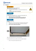
Page 16: ...tation lock Mechanical components may be damaged Only transport the device with mounted transportation lock Do not operate the device with built in transportation lock NOTICE N11 0017 Damage to components Transport Mechanical or electronic components may be damaged during transport The device must not be knocked shaken or thrown during transport Move the device gently during transport Fig 1 Unscre...

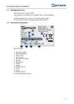
Page 17: ... in the Technical data chapter The machine must be secured before putting it into operation 3 8 Description of type plate Fig 2 Type plate 1 Device designation 2 Year of manufacture 3 Article number 4 Serial number 5 Manufacturer s address 6 CE mark 7 Disposal sign 8 Barcode 9 Voltage 10 Supply frequency 11 Output 12 Current 13 Number of fuses 14 Fuse design and fuse rating 1 2 3 4 5 6 7 8 9 10 11...

Page 18: ...g loss High sound level A high sound level may arise depending on the type of material and the duration of sample division Excessive noise in terms of intensity and duration can cause impairments or lasting damage to hearing Ensure you take suitable noise protection measures Wear hearing protectors when there is loud or persistent noise Target group User operating company operators Machine type de...

Page 19: ...les Continuous module For 1 divided sample with rejection mechanism Batch module Module for 6 divided samples 5 10 litres per segment Module for 8 divided samples 3 75 7 5 litres per segment Module for 10 divided samples 3 6 litres per segment 4 3 Feed size Vi Vibratory feeder up to 30 mm Vibratory feeder with splashback up to 15 mm 4 4 Rated Power 370 W Ensure that the voltage and frequency of yo...

Page 20: ... are mainly influenced by the machine speed the material being ground and the grinding set Workplace related emissions value LpAeq up to 75 dB A Sound power level LWA 98dB A Measurement conditions Continuous module Grinding material 5000 ml sand particle size 1 mm Sound level meter Brüel Kjaer 2237 Controller 4 7 Degree of Protection IP50 4 8 Protective Equipment The machine can only be operated w...

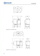
Page 21: ...Technical data 21 4 11 Installation drawing Fig 3 PT 300 Housing door closed Fig 4 PT 300 Housing door open ...

Page 22: ...Technical data 22 Fig 5 PT 600 Housing door closed Fig 6 PT 600 Housing door open ...

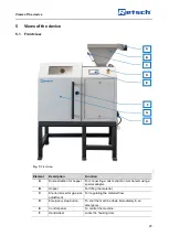
Page 23: ...r connecting a dust extraction mechanism using a special adapter B Hopper For filling the material C Knurled screw for gap size adjustment For regulating the material flow D Emergency stop button To shut the machine down immediately in an emergency E Control panel To control the machine F Hand wheel Locks the housing door B A C E F D G H ...

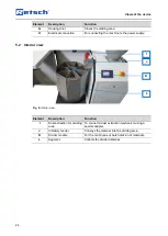
Page 24: ...wer supply 5 2 Interior view Fig 8 Interior view Element Description Function I Dust extraction for dividing area To connect a dust extraction mechanism using a special adapter J Vibratory feeder Conveys the material into the dividing area K Divider module For the continuous or batch division of materials L Segment Collects the divided material I K L J ...

Page 25: ...ons and parameters 6 Operating the device CAUTION C7 0006 Risk of injury Sample material that is harmful to health Sample material that is harmful to health can injure people illness contamination Use suitable extraction systems with sample material that is harmful to health Use suitable personal protective equipment with sample material that is harmful to health Take note of the safety data sheet...

Page 26: ...evice Fig 10 Opening the housing door Turn the hand wheel F anticlockwise to unlock and open the housing door G 6 2 Closing the device Fig 11 Closing the housing door Turn the hand wheel F clockwise to close and lock the housing door G F F G G ...

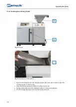
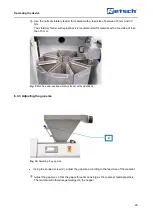
Page 27: ...the machine Always operate the machine with a divider module Do not overload the machine Check the amount of material in the segments of the divider module regularly while the machine is running Fig 12 Continuous divider module with one segment Fig 13 Batch divider module with eight segments Place the desired divider module K into the dividing area Fit the relevant number of segments L in the divi...

Page 28: ...r Open the housing door G and swing the hopper B to one side in order to insert the vibratory feeder J into the slot Slide the vibratory feeder J as far as it will go into the slot Springs at the side secure the vibratory feeder J in the correct position Shut the hopper B again and close the housing door G J B G ...

Page 29: ... feed size of less than 15 mm Fig 3 Machine with inserted vibratory feeder with splashback 6 3 3 Adjusting the gap size Fig 16 Adjusting the gap size Using the knurled screw C adjust the gap size according to the feed size of the material Adjust the gap size so that the gap is three times as big as the coarsest material particle The material will otherwise get wedged in the hopper C ...

Page 30: ...chanism to the hopper A or the dividing area I if the properties of the material so require A special adapter for connecting a dust extraction mechanism is available from Retsch GmbH 6 4 Control panel Operating the machine 6 4 1 Start menu Press any function key Fig 18 Start menu machine is not ready for use A I ...

Page 31: ...dy for use Ready appears in the display once the housing door has been locked using the hand wheel The division process can be started by pressing F1 F4 Set Opens the settings 6 4 2 Settings Select F4 to go to the menu settings The division process can be configured using this menu The display then shows the following functions Fig 20 Settings selection menu 1 3 ...

Page 32: ...er pressing F4 the following setting appears on the display Fig 21 Settings selection menu 2 3 In this menu you can specify the desired number of revolutions per minute to be implemented by the divider module Speed number of revolutions of the divider module F1 1 Increases the speed F2 1 Reduces the speed F3 No function in this selection menu F4 Next Opens the next page of the menu Pressing F4 dis...

Page 33: ...ses the vibration intensity F2 1 Reduces the vibration intensity F3 No function in this selection menu F4 OK To the start menu After confirming you go back to the start menu Fig 23 Start menu Starting the division process Press F1 to start the division process 6 4 3 Starting the division process Once you have started the division process by pressing F1 the display initially shows the following vie...

Page 34: ...arted and you will return to the start menu The display shows the following view after the safety query has been started by pressing F1 soll das vielleicht after the division process has been started heißen Fig 25 Display during the division process The display shows information about the current division process Speed Speed in rpm Provides information about the set speed of the divider module Fee...

Page 35: ...leted The division process can be ended at any time by pressing F2 6 5 Finishing the division process Fig 26 Front view Fig 27 Interior view Once the division process has finished unlock the housing door G using the hand wheel F Open the housing door G Remove the segments L with the material individually from the divider module K F G K L ...

Page 36: ...ccessing it for cleaning or servicing purposes Clean the housing of the device with a damp cloth and if necessary with a household cleaning agent Pay attention that no water or cleaning agent enters the interior of the device 8 Maintenance WARNING W6 0000 Risk of death caused by an electric shock Strong voltage due to capacitor discharge Due to capacitor discharge on the frequency convertor the ma...

Page 37: ...nicians Retsch GmbH reserves the right to refuse the acceptance and to return the respective delivery at the expense of the sender 10 Disposal In the case of a disposal the respective statutory requirements must be observed In the following information on the disposal of electrical and electronic devices in the European Community are given Within the European Community the disposal of electrically...

Page 38: ...ered since August 13th 2005 For all devices delivered before August 13th 2005 the end user is responsible for the proper disposal Information on available accessories as well as the respective manuals are accessible directly on the Retsch GmbH homepage https www retsch com under the heading Downloads of the device Information on wear parts and small accessories can be found in the Retsch GmbH gene...

Page 39: ...15 24 Emergency stop button 23 Emissions 20 Explanations of the safety instructions 8 External fuse 15 F Feed size 19 Finishing the division process 35 Frequency 15 Front view 23 35 Fuse design 17 Fuse rating 17 G Gap size adjustment 23 General catalogue 38 General safety instructions 9 H Hand wheel 23 Hearing loss 18 Height 20 Hopper 23 28 Housing door 24 Humidity 14 I Inserting the divider modul...

Page 40: ... number 17 Service address 10 Settings 31 32 Small accessories 38 Sound level 18 Sound level meter 20 Sound power level 20 Spare parts 38 Start menu 30 31 33 34 Starting the division process 33 Supply frequency 17 T Target group 6 Technical data 18 Temperature fluctuations 13 Temperature range 14 Temporary storage 13 Transport 13 16 Transport damage 13 Transport lock 16 Transportation lock 16 Type...

Page 41: ......

Page 42: ...Copyright Copyright by Retsch GmbH Retsch Allee 1 5 42781 Haan Germany ...

Reviews: