


12
Intera 5.3
Getting to Know Sawyer
degrees. The closer you are to the edge of these limits, the greater the chance
the robot will be unable to train an action.
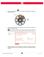
•
If you notice Sawyer cannot reach a location, try moving the location closer to
the robot, or re-train the location.
•
The training cuff can rotate 540 degrees. If, when training, the orientation of the
training cuff is twisted near its limit, the robot may have trouble when you run the
task.
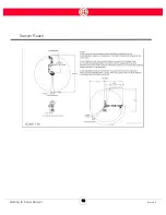
The possible vertical range of an action is reduced as you move closer to the edges of the
maximum available workspace of the robot.
The robot’s software, including collision avoidance, can also limit the movement and capabilities of
the arm. For example, you cannot incorrectly train the robot so the arm crashes into itself.
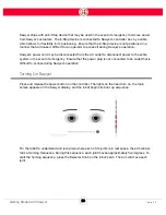
In Intera Studio, you can click on the Joints Tab to see the extent of rotation of each of Sawyer's
joints. A slider near either end of the slider range indicates proximity to a joint limit. You can also see
the joint position indicators on the right side of the robot’s display screen.
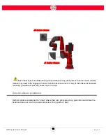
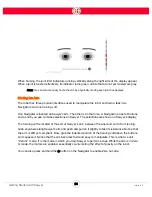
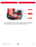
Head
Sawyer’s “head” is the LCD display that sits on top of the robot. It houses the Graphical User
Interface (GUI). The head also contains a camera and a light that communicates the robot’s
condition.
The head is back drivable. It has a motor in it, which means you can physically move the head
whether or not the robot has power. The head can be moved along the same joint/axis that it moves
itself. It rotates a total of approximately 350 degrees.
There are two modes for head movement: passive and active. Passive means you can move the
head manually. In active mode, the head automatically follows the movement of the training cuff.
IMPORTANT: It is relatively easy to move the head. Even a single tap of the finger can move it, so do
not use force when moving the head. When you feel resistance, stop.
Summary of Contents for Sawyer
Page 15: ...8 Intera 5 3 Getting to Know Sawyer Hardware Overview of Your Robot ...
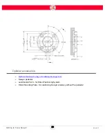
Page 16: ...9 Intera 5 3 Getting to Know Sawyer Dimensions ...
Page 17: ...10 Intera 5 3 Getting to Know Sawyer Sawyer Reach ...
Page 93: ...86 Intera 5 3 Train Pick and Place Patterns on the Head 11 Press OK to go to the next step ...
Page 104: ...97 Intera 5 3 Train Pick and Place Patterns on the Head You may now run the task ...
Page 134: ...127 Intera 5 3 TCP IP The Set To node in the Behavior Editor is used to output information ...
Page 138: ...131 Intera 5 3 Fieldbus Devices 3 Using a keyboard navigate to CONFIGURATION and press ENTER ...
Page 155: ...148 Intera 5 3 ...
Page 156: ...149 Intera 5 3 ...
Page 180: ...173 Intera 5 3 ...
Page 190: ...183 Intera 5 3 Fixed Data 112 From Robot ...
Page 206: ...199 Intera 5 3 Small Assembly 114 From Robot 115 To Robot ...
Page 207: ...200 Intera 5 3 Large Assembly 116 From Robot 117 To Robot ...
Page 208: ...201 Intera 5 3 Floats 118 From Robot 119 To Robot ...
Page 209: ...202 Intera 5 3 Strings 120 From Robot 121 To Robot ...
Page 218: ...Z Zero G button 16 17 Zero G mode 24 Zero Gravity mode 17 zoom reset 42 ...
Page 219: ......
Page 220: ...Last updated June 18 2018 Intera 5 3 User Guide Getting Started Rev A ...