


164
Intera 5.3
Performance with Advanced End-effectors
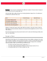
If one of the three conditions stated at the beginning of the previous section is true, the user should
refer to a separate set of payload vs. acceleration plots for end-effector design. It is unnecessary to
use the following charts when the reach is less than 1 m, the payload is under 2 kg and the offset
from the J6 axis is less than 10 cm.
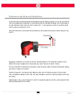
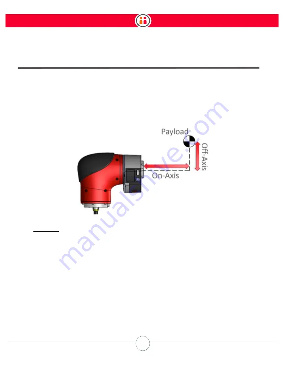
First, let’s define the on-axis and off-axis distances with respect to Sawyer’s cuff according to Fig-
ure D-5.
Figure D-5: Illustration of on-axis and off-axis payload positions. The payload includes the end-
effector and object weight and is represented as a point mass at its center of mass.
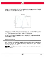
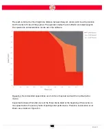
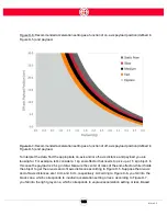
The recommended combinations of payload, center-of-mass position and joint acceleration setting
are shown in Figures D-6 and D-7.
Similar to Figure D-4, the regions with different colors are not mutually exclusive. For example,
when acceleration setting is set to
fast
, the valid workspace covers the dark blue region and the yel-
low region.
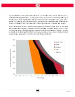
Unlike Figure 4, the
x
-axis in Figure D-6 and D-7 represents payload, and the
y
-axis represents the
offset payload position (not
reach
).
Summary of Contents for Sawyer
Page 15: ...8 Intera 5 3 Getting to Know Sawyer Hardware Overview of Your Robot ...
Page 16: ...9 Intera 5 3 Getting to Know Sawyer Dimensions ...
Page 17: ...10 Intera 5 3 Getting to Know Sawyer Sawyer Reach ...
Page 93: ...86 Intera 5 3 Train Pick and Place Patterns on the Head 11 Press OK to go to the next step ...
Page 104: ...97 Intera 5 3 Train Pick and Place Patterns on the Head You may now run the task ...
Page 134: ...127 Intera 5 3 TCP IP The Set To node in the Behavior Editor is used to output information ...
Page 138: ...131 Intera 5 3 Fieldbus Devices 3 Using a keyboard navigate to CONFIGURATION and press ENTER ...
Page 155: ...148 Intera 5 3 ...
Page 156: ...149 Intera 5 3 ...
Page 180: ...173 Intera 5 3 ...
Page 190: ...183 Intera 5 3 Fixed Data 112 From Robot ...
Page 206: ...199 Intera 5 3 Small Assembly 114 From Robot 115 To Robot ...
Page 207: ...200 Intera 5 3 Large Assembly 116 From Robot 117 To Robot ...
Page 208: ...201 Intera 5 3 Floats 118 From Robot 119 To Robot ...
Page 209: ...202 Intera 5 3 Strings 120 From Robot 121 To Robot ...
Page 218: ...Z Zero G button 16 17 Zero G mode 24 Zero Gravity mode 17 zoom reset 42 ...
Page 219: ......
Page 220: ...Last updated June 18 2018 Intera 5 3 User Guide Getting Started Rev A ...