


© RESOL 11294 flo
wsol_d_d_he
.monen.ind
d
FlowSol D / D HE
| 14
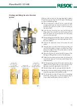
11.3 Operation
Adjustment mode
In the adjustment mode, different functions are selected
and values are adjusted. Press button 3 for 2 seconds in
order to access the adjustment menu.
Î
Use button 1 and 2 respectively to select the function
to be activated or the adjustment value and confirm
with button 3.
Adjusting a value:
Î
Select the value with button 1 or 2
Î
briefly press button 3; the adjustment range is shown
in form of a bar
Î
adjust the selected value with buttons 1 or 2; the value
is shown on the bar by means of a slide
Î
Briefly press button 3 to confirm the adjustment.
Î
Press button 3 again in order to store the adjustment
and to get back to the adjustment menu.
If button 3 is not pressed after an adjustment has been car-
ried out, the display changes back after some seconds. The
adjusted value will then not be stored.
Selecting a function or an option:
Î
Select a function or an option with button 1 or 2
Î
briefly press button 3.
Î
Select „Yes“ in order to activate the selected function,
select „No“ to deactivate the function.
Î
Briefly press button 3 to confirm the selection.
Î
Press button 3 again in order to store the selection.
An activated function is indicated by means of a marked
checkbox. The corresponding adjustment values are also
displayed.
Yes
No
Collector cooling:
Collector cooling
Tcolmax
110 °C
∆
Tcolmax
5,0 K
Balance / adjust. values:
x
90
0
60 °C
Storage max. temp.
Î
In order to access the display mode, keep button 3
pressed for 2 seconds.
If no button is pressed in the adjustment mode within 2
minutes, the display automatically changes to show the
status display.
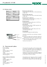
1
2
3
backward
SET
(selection-/
adjustment mode)
forward
11.4 User code
Expert
Code 0077
All display and adjustment values are shown, all adjustments
can be altered.
In order to enter the user code, scroll down in the sub-
menu „balance and adjustment values“ until you reach the
item „relay mode“, then keep button 2 pressed for 2 se-
conds.
Note:
After the menu item „user code“ has been selected, this
code must be entered.
If the expert user code is not entered, the expert menu will
not be displayed.
If the expert menu is activated, it will be accessible for 60
minutes. If the controller is restarted, the expert menu can-
not be accessed. By means of the option „Expert“, in the
expert menu, the expert menu can be permanently enabled.