en
4
2
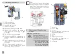
Mounting the station
10
11
12
13
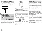
10 Wall mounting bracket
11 Back half of the insulation
12 Front half of the insulation
13 Hinged controller panel
Î
Determine the mounting site of the station.
Î
Mark the drill holes by means of the template en-
closed, then drill and insert wall plugs (see fi gure
to the right).
Î
Take the station out of the packaging.
Î
Remove the front half of the insulation. Leave the
pump station attached to the back half of the in-
sulation!
Î
Fasten the pump station to the wall with the en-
closed screws. For this purpose, use a crosshead
screw driver.
Î
Fold the hinged controller panel to the left.
Î
Connect the pipework between pump station
and store and collector respectively.
Note
All connections are already tightened such
that they usually do not have to be tightened
again. However, during commissioning of the
system all connections have to be checked
for leaks (pressure test).
3
Flushing and fi lling the solar
system
WARNING!
Scald danger!
Pressure surge damage!
If the medium enters strongly heat-
ed, empty collectors, pressure surg-
es caused by evaporation can occur.
Î
In order to prevent the solar
fl uid from vaporising inside
the collectors, do not fi ll
or fl ush the system during
times of strong irradiation!
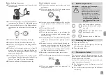
1 Safety valve
2 Pressure gauge
3 Drain valve
4 Ball valve (return) with thermometer and
integrated non-return valve
5 Fill valve
6 Pump
7 Grundfos Direct Sensor
TM
8 Ball valve (fl ow) with thermometer and
integrated non-return valve
9 Air separator
5
4
3
1
2
6
7
9
8


