Making quality of care easy
Respiratory Care solutions
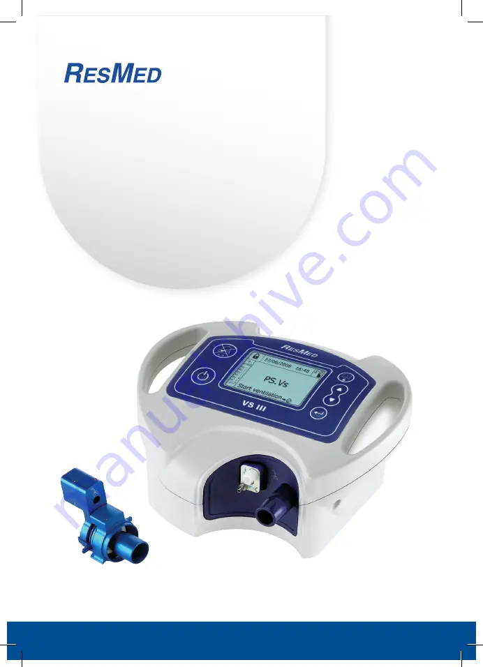
VS III™
User Manual
English
Page 1: ...Making quality of care easy Respiratory Care solutions VS III User Manual English...
Page 2: ...Making quality of care easy Respiratory Care solutions...
Page 3: ...the mask 11 3 4 Example of a fully assembled system 11 4 How to use 12 4 1 Starting ventilation 12 4 2 Switching programs during ventilation 13 4 3 Viewing data during ventilation 14 4 4 Setting the d...
Page 4: ...iv...
Page 5: ...1 Definitions This manual contains special terms and icons that appear in the margins to draw your attention to specific and important information CAUTION Explains special measures for the safe and e...
Page 6: ...e of inappropriate accessories is likely to affect the operation of the device If you have any questions about setting up operating or maintaining your ventilator or its accessories contact your HME p...
Page 7: ...It must not be disposed of with ordinary municipal waste Contact your HME provider for more information The above are general warnings Other specific warnings and notes will be found throughout the te...
Page 8: ...f circuit support for double circuits see next figure Figure 3 Detailed view of circuit support double circuit P Control panel screen and keypad Respiratory circuit connection area Air outlet Single c...
Page 9: ...the rear of the device Figure 4 Rear view of the device Device control panel The device control panel comprises an LCD screen and a keypad Figure 5 Detailed view of the control panel The keypad consi...
Page 10: ...stay on the screen Press the button a second time to remove them Either the orange or red LED will start flashing depending on the type of alarm Menu button Opens the menu viewing data setting date a...
Page 11: ...g it to the device see Connecting the respiratory circuit on page 9 3 Connection procedures The device must be placed on a flat surface Ensure the area is dust free and cleared of any objects that cou...
Page 12: ...to the mains power supply Note Skip step 2 if using a power supply unit with a fixed power cord Your device is now in standby mode WARNING The power cord is equipped with a push pull locking connecto...
Page 13: ...s connected to the device you can connect the mask to the other end of the tube Option 2 Single circuit with expiratory valve and pressure line 1 Connect the air outlet firmly to one branch of the cor...
Page 14: ...to the other end of the circuit Option 3 Double circuit 1 Firmly connect one limb of the circuit to the air outlet 2 Then connect the other limb Figure 10 Connecting a double circuit P 1 2 3 2 3 Expi...
Page 15: ...you have any questions about connecting your respiratory circuit 3 3 Connecting the mask Refer to the instructions given by your physician or HME provider CAUTION It is essential to use only the mask...
Page 16: ...nt ventilation program technical data and the Event and Alarm Log Set the date and time 4 1 Starting ventilation Figure 12 Turning the device on self test performed and ventilation start screen displa...
Page 17: ...Prog2 PS Vt Prog1 PS Vs Stop Confirmation cmH2O 9 60 50 40 30 20 10 0 Confirm No Yes Program change LP While the device is delivering ventilation under Prog1 press On the program change confirmation...
Page 18: ...s Alarm thresholds Settings 27 06 2011 16 48 cmH2O 0 60 50 40 30 20 10 0 DATE TIME ALL EVENTS CODE Events 1 to 8 of 17 Alarms only Scroll 21 25 21 01 3 2 1 0 High FiO2 FiO2 High FiO2 FiO2 Low FiO2 FiO...
Page 19: ...Day 25 Month 8 Year 2008 Hour 10 Minute 13 Date and Time Setting Day 25 Month 8 Year 2008 Hour 10 Minute 13 Back PS Vs Menu View settings alarms Technical information Events Alarms Log Date and Time S...
Page 20: ...0 20 10 0 cmH2O 6 60 50 40 30 20 10 0 Stop ventilation 1s Turn off ventilator Cancel Disconnect O2 before stop Confirm PS Vs Stop Stop Start ventilation Start ventilation PS Vs Prog1 PS Vs Prog2 PS Vt...
Page 21: ...30 20 10 0 PS Vs Start ventilation 27 09 2008 19 18 cmH2O 9 60 50 40 30 20 10 0 PS Vs Stop cmH2O 0 60 50 40 30 20 10 0 cmH2O 9 60 50 40 30 20 10 0 Confirmation Confirmation Turn off ventilator 1s Can...
Page 22: ...en the device casing Repairs and internal servicing should only be performed by an approved technician Component Frequency Maintenance Respiratory circuit Follow specific recommendations from your HME...
Page 23: ...r HME provider Table 3 Ventilation alarms not an exhaustive list Alarm name Cause Solution Mains Disconnect The mains power cord has been disconnected Reconnect the mains power cord Ext Battery Lost T...
Page 24: ...HME provider if this alarm persists Low Vti or Low Vte Low inspired volume or low expired volume Check your circuit High Vti High inspired volume Check your circuit and make sure there are no leaks A...
Page 25: ...7 3 Power supply Mains power Input 100 240 V AC 50 60 Hz Max 1 8 A Output 30 V DC 2 33 A CAUTION Use only the power supply unit provided with the device Internal battery NiMH 24 V 2 1 Ah Internal bat...
Page 26: ...essure 600 1100 hPa Extraordinary use Operating temperature 5 C to 40 C Note Between 5 C and 5 C it takes the device 30 minutes to reach optimal performance To obtain optimal performance immediately i...
Page 27: ...coloured black or white depending on the charge level Down arrow indicates the internal battery is discharging Indicates the Patient menu Indicates that the LP expi alarm was deactivated following the...
Page 28: ...24...
Page 29: ...dust filter 7 E Event and alarm log 14 expiratory valve 9 10 H HME provider 1 I internal battery 8 K keypad 5 L LEDs 5 M maintenance dust filter 18 headgear 18 mask 18 respiratory circuit 18 mask 11...
Page 30: ...26...
Page 31: ...Making quality of care easy Respiratory Care solutions...
Page 32: ...Protected by the following patents FR 2839893 US 7891353 VS III is a registered trademark of ResMed Paris The technical specifications may be changed without notice 2012 ResMed Paris 0123 Global lead...