background image


XCell™ C410:V3 Controller 

User Guide 


32          repligen.com           UG-C410v3-06 


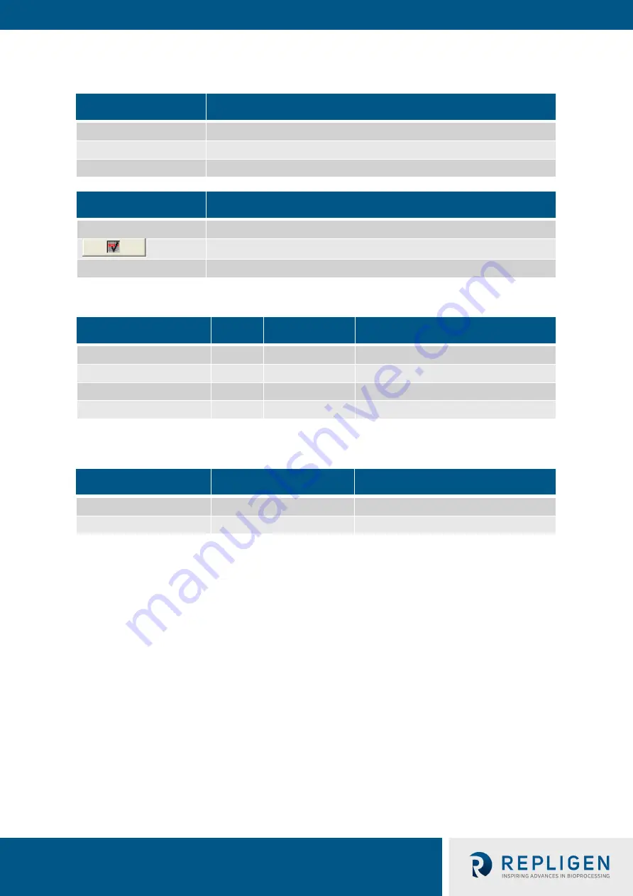
Table 12. The Alarm screen display parameters 

Field


Description


Time


Indicates time of alarm


Date


Indicates date of alarm


Text


Describes alarm


Button


Description


Horn acknowledge


Press to turn off horn


Select highlight Warning/Alarm message and press to remove


All Primary


All Primary screen buttons are displayed to navigate  to those screens


Table 13. Two (2) Pump controller status relay states 

XCell ATF® Device states  State #  Relay #1 

Relay #2 

Power Off/Alarm 

Off 

Off 

Power On/Standby 

Off 

On 

Power On/Running 

On 

On 

Power On/Warning 

On 

Off 


Table 14. Two (2) Pump interlock relay states 

Harvest pump state


Relay #3


Relay #4


Active


On


On


Not Active


Off


Off


An isolated Form C contact for each relay is provided for the end user to connect to any remote 

monitoring system. The Harvest pump is activated to Run mode, only and only if Relay #1 is ON, i.e. 

in Power On/Running state #C or Power On/Warning state #D. 


The following is a list of XCell™ C410:V3 Controller warnings that can occur during normal operation: 


Flow Set Point cannot be reached. P-Flow Regulator (PV1) above maximum operating 

setting. 


Flow Set Point cannot be reached. P-Flow Regulator (PV1) below minimum operating 

setting. 


Exhaust Set Point cannot be reached. E-Flow Regulator (PV2) above maximum operating 

setting. 


Exhaust Set Point cannot be reached. E-Regulator (PV2) below minimum operating setting. 


Summary of Contents for XCell C410:V3

Page 1: ...1 UG C410v3 06 XCell C410 V3 Controller User Guide For use with XCell ATF 4 Device XCell ATF 6 Device XCell ATF 10 Device ...

Page 2: ... incidental or consequential damages in connection with the furnishing performance or use of this material No part of this document may be photocopied reproduced or translated to another language without the prior written consent of Repligen Corporation Products are not intended for diagnostic or therapeutic use or for use in vivo with humans or animals For further information please contact Repli...

Page 3: ...stem User Guide XCell C410 V3 Controller User Guide 3 UG C410v3 06 Contents 2 1 1 Filtration assembly 14 4 3 1 S Line HFM insertion 43 4 3 2 I Line HFM insertion 43 7 4 1 Bi annual maintenance 48 7 4 2 Every four years 49 ...

Page 4: ...KrosFlo TFDF Lab System User Guide XCell C410 V3 Controller User Guide 4 UG C410v3 06 ...

Page 5: ...ow values 40 Table 21 Cycle time vs Flow rate 49 Table 22 Access levels to the XCell C410 V3 Controller 50 Table 23 Monitor points list 62 Table 24 Input Output list 64 Table 25 Alarm list 66 Table 26 Spare parts 67 List of figures Figure 1 Filtration assembly connection to C410 V3 Controller and a bioreactor side port 8 Figure 2 XCell ATF Device pump cycles 9 Figure 3 XCell C410 V3 Controller XCe...

Page 6: ... machine interface PA Pump air PL Pump liquid PRV Pressure regulator valve SM Screen module SUBs Single use bioreactors TFDF Tangential flow depth filtration California Proposition 65 Warning WARNING This product can expose you to chemicals including Cadmium which is known to the State of California to cause cancer and birth defects or other reproductive harm For more information go to www P65Warn...

Page 7: ...tor Adaptor adaptor between the Connection Assembly and bioreactor port Typical ports connectors adaptors for stainless steel bioreactors include an Ingold type port or if a single use bioreactor SUB then a disposable aseptic connector DAC or equivalent A typical configuration of the XCell ATF Device is shown in Figure 1 The filter housing accepts either a HFM with pore sizes from 30 kD to 0 5 mic...

Page 8: ... will be through the filtration device The second pump chamber the pump air PA chamber is connected to the pump flow control system Typically controlled addition of compressed air into the PA chamber increases the pressure in the chamber relative to the process vessel forcing the flexible diaphragm partitioning the two chambers to move into the PL chamber and towards the vessel Liquid in the PL ch...

Page 9: ...e PL chamber When vessel pressure is limited it may be supplemented with vacuum In either of the above schemes one is driving the liquid from the vessel to the diaphragm pump by increasing the pressure in the vessel relative to the diaphragm pump WARNING Glass bioreactors or single use bioreactors SUBs unless otherwise specified by the manufacturer of the vessel should not be pressurized Such vess...

Page 10: ...XCell Controller Description XCell ATF 4 Stainless Steel XCell C410 4V3 XCell C410 V3 C410 Controller for XCell ATF 4 Device with air tubing XCell C410 4V3 GMP XCell C410 V3 C410 controller for XCell ATF 4 Device with air tubing and standard GMP documentation and FAT XCell C410 4V4B GMP Profibus configured XCell C410 V4B Controller with power separation for XCell ATF 4 Device with air tubing stand...

Page 11: ...XCell C410 V3 Controller User Guide 11 repligen com UG C410v3 06 1 3 XCell ATF Device interconnectivity drawing Figure 3 XCell C410 V3 Controller XCell ATF 10 SS pump housing and pressure relief valve ...

Page 12: ...eam SIP 30lbs hr Applicable only to a steamable connection between XCell ATF Device and bioreactor vessel Condensate drain For SIP condensate drainage Altitude 2000 m This product has been assessed for a maximum altitude of 2000 m Pollution degree Pollution degree 2 This product is intended to be used in an environmental of pollution degree 2 Pollution degree 2 area is normally where only noncondu...

Page 13: ...e use Device 38 in 12 in 10 in XCell ATF 10 Single use Device 38 in 18 in 16 in Note Indicated dimensions are estimates for the filtration assembly as the connection to the bioreactor the connections to the controller and to accessories can affect height and effective area Component Estimated weight Comments C410V3 Controller Pneumatic Box 13 Kg Weight of the P Box will vary depending on the parti...

Page 14: ...the facility One can envision the P Box in proximity to the filtration assembly while the E Box positioned distant to the filtration assembly possibly mounted on a wall or a skid 2 1 1 Filtration assembly This includes the diaphragm pump Filter Housing connection to the bioreactor harvest line pump air inlet assembly stand plus all the housing accessories as specified in the part list Figure 4 Pne...

Page 15: ... POWER ON OFF selected switch n Illuminated system STOP push button o Alarm relay outputs 2 p Harvest pump relay outputs 2 q Ethernet plug 2 2 Primary pneumatic services Air inlet e Located on the P Box and provides an inlet to house compressed air source Recommended minimum air pressure requirement is 50 psi 3 4bar Somewhat higher inlet pressures may be required as needed to generate higher flow ...

Page 16: ...al range of gauge is 0 to 30inHg 0 95 bar It shows primary vacuum pressure status 2 3 Primary electric services Electric plug j Located on the E Box Electric power standard 100 240V AC 50 60Hz Power switch m Located on E Box Power indicator Light same as the power switch Lights green when power is ON Stop button a n Located on the P Box and E Box Either Stop button causes the system cease operatio...

Page 17: ...the XCell ATF Device The OPC Client Software will control the XCell ATF Device remotely and or read the status of the XCell ATF Device Examples of OPC Client Software include Microsoft Excel WinCC HMI by Siemens and FTView HMI by Rockwell Automation The acronym OPC comes from OLE Object Linking and Embedding for Process Control Since OLE is based on the Windows COM Component Object Model standard ...

Page 18: ...ults i e warning and alarms 4 Process trending When an input box is highlighted and pressed a number pad or keyboard will appear on screen to enable data input For numerical entries as the value is being typed a Min and Max range dialog box appears showing the user the acceptable value range Any value outside the min max range or any text strings or letters is not accepted The OIT will display the...

Page 19: ...tion of screens and buttons Figure 6 Log on screen Log on screen appears when the C410 V3 controller is powered up Click on LOG ON to bring up User Password Dialog Box and Keyboard For first time use enter ADMIN for USER and 1234 for PASSWORD Figure 7 Log on screen and password ...

Page 20: ...hragm pump a When starting the diaphragm pump a dialog box will appear to enable the user to start with current settings start with default settings or cancel and return to the main screen b When stopping the diaphragm pump a dialog box will appear that enables the user to confirm the stop command or to cancel and return to the main screen 3 Access other screens based upon password security levels...

Page 21: ...cycle Sec PV1 Field Entry Displays current position set point of flow proportional valve 0 100 PV2 Field Entry Displays current position set point of exhaust proportional valve 0 100 PRV1 Field Entry Displays current setting of automatic pressure regulator 0 to 35 psi PRV2 Field Entry Displays current setting of automatic exhaust regulator 15 to 0 psi P2 Status Display Displays current pressure be...

Page 22: ...rocess setup e g different bioreactor configuration and parameters This minimizes the number of cycles taken by the controller to reach the desired flow rate At any selected flow rate default simply resets the control parameters to factory preset values Cancel will return to the main screen without any action taken Stopping the pump the following dialog box will appear 3 3 Set up From the Set up S...

Page 23: ...om UG C410v3 06 Figure 9 Basic Set up screen From the Basic Set up screen an Engineer Administrator can Set initial controller Set up Change Hi and Lo Alarm set points Change Process Parameters Access other screens based upon password security levels ...

Page 24: ...es the system will go into an Alarm state should the condition for the alarm persists for the set elapsed time defined in this parameter This will put system in a halt condition Pump parameters Groups diaphragm pump parameters P Pressure offset psi Pressure cycle Pressure Offset or Over pressure Set Point P OSP1 value psi above P2 to switch from flow or pressure cycle to exhaust E Pressure offset ...

Page 25: ... FLOW sec Minimum limit for PFLOW set point Seconds Max E FLOW LPM Maximum limit for EFLOW set point LPM Max E FLOW sec Maximum limit for EFLOW set point Seconds Min E FLOW LPM Minimum limit for EFLOW set point LPM Min E FLOW sec Minimum limit for EFLOW set point Seconds PV1 Max Maximum operating limit for PV1 PV1 Min Minimum operating limit for PV1 PV2 Max Maximum operating limit for PV2 PV2 Min ...

Page 26: ...uide for the operator This information should be reviewed by all users before operating the XCell C410 V3 Controller Table 8 The Start up Guide screen display parameters Button Description Basic Set up Press to switch to Basic Set Up screen Advanced Set up Press to switch to Advanced Set Up screen Calibration Instrument calibration All Primary All Primary screen buttons are displayed to navigate t...

Page 27: ...oint calibration Note this should only be performed by a qualified metrology personal or Repligen Field Service Engineer Table 9 Calibration screen display parameters Field Description Engineering Units Enter the Engineering Units for the selected analog input Minimum Engineering Value Enter the Minimum Engineering value for the selected analog input Maximum Engineering Value Enter the Maximum Eng...

Page 28: ...on Point This button will capture the raw input value for the second point for the selected analog input Actual Value This button will finalize the two point calibration performed for the corresponding line Basic Set Up Press to switch to Basic Set Up Screen Advanced Set Up Press to switch to Advanced Set Up Screen Help Guide Press to switch to Start Up Guide Screen Accept Discard change Accept Ch...

Page 29: ...Field Description Max Enter maximum value for the chart Y Axis Min Enter minimum value for the chart Y Axis Table 11 Trend screen controls Button Description Scrolls back to the beginning of the trend recording The start values with which the trend recording started are displayed Zooms into the displayed time section Zooms out of the displayed time section Scrolls back one display width Scrolls fo...

Page 30: ...pligen com UG C410v3 06 Figure 15 PV PRV P2 P3 P4 P5 W1 Trend screens These screens monitor in real time the specific analog signal Trend buttons select trend to display All screens have the following screen control options listed in Table 11 ...

Page 31: ...pump While the PLC records the output from the load cell in milliseconds the computer HMI is much slower and refresh rate is about once every 0 5 1 0 second therefore while one may not observe the details of the pump cycle on the HMI typically between 4 10 seconds half cycle the PLC will continue to monitor the rapid weight change 3 6 Alarms Figure 16 Alarm screen The operator can view XCell C410 ...

Page 32: ...Off Table 14 Two 2 Pump interlock relay states Harvest pump state Relay 3 Relay 4 Active On On Not Active Off Off An isolated Form C contact for each relay is provided for the end user to connect to any remote monitoring system The Harvest pump is activated to Run mode only and only if Relay 1 is ON i e in Power On Running state C or Power On Warning state D The following is a list of XCell C410 V...

Page 33: ...ng of User ID s and passwords There are three 3 levels of security 1 Operator 2 Engineer 3 Administrator The XCell C410 V3 Controller includes one 1 Administrator User ID and 1 predefined Engineer Level and 1 predefined Operator Level User ID s Only the administrator will have security access to add edit delete all other User ID s by touching the appropriate fields Each User ID includes a field fo...

Page 34: ... level of security allows different levels of access to the XCell C410 V3 Controller control functionality please refer to Appendix 2 for details Figure 18 Basic Administration screen Note Software version numbers shown above may not match the most current software revision Available from the Admin screen It allows the Administrator to reset Pump Cycle count It also allows manual control of Flow C...

Page 35: ...formation Elapsed Time Displays Elapsed time of current batch run Time is reset by changing Batch Name Cycle Count Displays diaphragm pump cycle count of current batch run User ID Displays Users ID Engineer or Administrator Batch Set Up Set Batch Name and reset cycle count Name Click on field to change batch name Button Description Cycle Count Reset Resets cycle count to zero in Batch Data field A...

Page 36: ...le 17 Batch Info Algorithm display parameters Field Description Algorithm performance Tracks cycle change mechanism Primary method Shows cycle count triggered by Set point method tracks pressure cycle and exhaust cycle counts Overtime Shows cycle count triggered by overtime tracks pressure cycle and Exhaust cycle counts Overflow Shows cycle count triggered by overflow tracks pressure cycle and Exh...

Page 37: ...ording to the following relationship Pump displacement volume L Cycle time sec 60 Flow rate LPM The pump displacement volumes with no pressure difference across the diaphragm are XCell ATF 4 Device 0 44 L XCell ATF 6 Device 1 2 L XCell ATF 10 Legacy Device 5 1 L XCell ATF 10 Device 6 0 6 7 L See also Appendix 1 Cycle time vs Flow rate Therefore selection of a Flow Rate L min by a user using an XCe...

Page 38: ...the Error The error will cause pressures to be changed to affect the flow positive or negative respectively to and from the pump to match flow set point for the next cycle If the new value for PRV1 and or PRV2 exceed their set pressure limits e g PRV1 0 to 30 psi PRV2 0 to 14 5 psi then the respective PV1 and PV2 will adjust incrementally e g by user defined increments in the Basic Set Up screen u...

Page 39: ...rm Set Point 7 psi Alarm Delay x10 msec 50 for both Pump parameters Value P Pressure Offset psi 0 5 E Pressure Offset psi 0 5 P Delay 70 E Delay 70 P Overtime 120 E Overtime 120 P PV Step size 3 E PV Step size 3 Press accept changes Table 19 Advanced Set Up screen values Field Values User Set point range XCell ATF 4 Device XCell ATF 6 Device XCell ATF 10 Legacy Device XCell ATF 10 Device Max P Flo...

Page 40: ...entries and connections than restart If problem persists check the following a The P between PRV1 P2 should be greater than P Pressure Offset and P between PRV2 P2 should be less than E Pressure Offset If not manually lower PV in small increments b Flow is too rapid A flow that is too rapid during the exhaust cycle can be readily detected on the P2 trend by a rapid decline in pressure following a ...

Page 41: ...er to the diaphragm pump at this point 6 Power On the E Box Wait for system to boot up and display the XCell ATF Device Log On screen 7 Log On the main screen will be displayed Proceed to the Set Up screen 8 Enter settings Note XCell ATF Device selection Select XCell ATF 6 Device Note reactor pressure and height enter 0 and measured difference between diaphragm pump clamp and vessel liquid level i...

Page 42: ...Disconnect any sensors from the filtration assembly to P Box If necessary remove the P Box from the proximity of the filtration assembly Close and disconnect the filtrate line Disconnect the filtration assembly from the vessel as follows 1 Securely close both bivalves connecting the filtration assembly to the vessel 2 Drain liquid from the connection Optionally purge the connection with water stea...

Page 43: ... housing end 2 Expose HFM at the filter housing end distant to Drain port in proximity to the filtrate harvest port 3 Place an O ring in the exposed HFM O ring groove 4 Press the HFM with O ring firmly into the housing Assure the O ring is inserted smoothly and uniformly Lubricate with WFI to facilitate this process 5 Press until the HFM O ring groove is exposed at the other end the Drain nozzle e...

Page 44: ...pheres together 7 Secure the diaphragm pump to the stand Diaphragm replacement procedure for the XCell ATF 10 Device 1 The diaphragm within the diaphragm pump of the XCell ATF 10 Device contains a short right angle bend on the diaphragm periphery which mates with a counterpart groove in the PA pump hemisphere flange therefore for the XCell ATF 10 Device these two parts are assembled first The two ...

Page 45: ...ng sterilization is minimized This assures free flow of steam into the unit and unobstructed pressure equilibration between all compartments within the unit particularly the filtrate and retentate sides are at the same pressure during the sterilization and cool down procedures Note Use high capacity vent filters to allow unobstructed high flow of steam into and from the system Please refer to the ...

Page 46: ... and Autoclave Guide for detailed guidance on the entire procedure including the recommended filter integrity test procedures and specifications The recommended cycle will require custom programming to incorporate a 90 minute preheat and 2 3 moderated prevac pulses to control the rate of temperature change within the cartridge to a rate of 1 C min during the warmup Repligen recommends that during ...

Page 47: ...One must assure however that the Harvest line has been prepared with the appropriate tubing for use with the filtrate harvest pump One may also prepare the Filtrate Harvest line post autoclaving using a tube welder If a tube welder cannot be used a disposable sterile coupling may be used 6 Connection to bioreactor Two types of connections between filtration assembly and bioreactor are commonly ava...

Page 48: ...ed every two or three runs Replacement kits are available from Repligen HFM Filter O rings should be replaced with each new filter For pump line air supply and vacuum source all O rings and gaskets should be replaced periodically An approved lubricant may be used to facilitate coupling of parts containing an O ring seal 7 4 Controller maintenance 7 4 1 Bi annual maintenance 1 P2 verification or ca...

Page 49: ...ice Cycle Time vs Flow Rate Table 21 Cycle time vs Flow rate XCell ATF Device Pump volume L XCell ATF 4 Device 0 4 XCell ATF 6 Device 1 3 XCell ATF 10 Legacy Device 5 1 XCell ATF 10 Device 6 0 Cycle time sec Flow rate L min 4 6 0 18 8 76 5 90 0 6 4 0 12 5 51 0 60 0 8 3 0 9 4 38 3 45 0 10 2 4 7 5 30 6 36 0 12 2 0 6 3 25 5 30 0 14 1 7 5 4 21 9 25 7 16 1 5 4 7 19 1 22 5 18 1 3 4 2 17 0 20 0 20 1 2 3 ...

Page 50: ...ending PV1 Input value Not allowed PRV1 Input value Not allowed PV2 Input value Not allowed PRV2 Input value Not allowed P2 General View only View only General Allowed Alarms Silence alarm General Not allowed Clear alarm General Not allowed Overview General View and allowed to adjust Min and Max Trending Process Trend General View and allowed to adjust Min and Max P2 Trend General View and allowed...

Page 51: ...ccess Not allowed Main screen Users General Access Not allowed General Access General Access Upon Login Start stop General Allowed P Flow status LPM SP Allowed LMP PV View only Sec Calculated View only Sec Actual View only LPM SP View only E Flow status LMP PV Allowed Sec Calculated View only Sec Actual View only PV1 Input Value Not allowed PRV1 Input Value Not allowed PV2 Input Value Not allowed ...

Page 52: ...ata Name View only Elapsed time View only Cycle count View only User ID View only Batch Setup Name Allowed Reset Allowed Batch Info Algorithm General Access General Allowed Algorithm Performance Primary method Reset only Override time Reset only Overflow Reset only Set Up General General Allowed Set Up Basic Controller Setup Pump Model Allowed to adjust Control Mode Allowed to adjust Alarm Delay A...

Page 53: ...ust LPM and seconds field Accept changes Allowed Discard changes Allowed PV1 Allowed to adjust min and max Output CV limits General access Network Setup General Access Analog Input P2 PV2 Allowed to adjust min and max PRV1 psi Allowed to adjust min and max PRV2 psi Allowed to adjust min and max TCP IP Accept changes Allowed Discard changes Allowed General Allowed IP Address Not allowed Subnet Mask...

Page 54: ...d Calibration 1 Eng Units Not Allowed 5th Point Not Allowed Actual Value Not Allowed Accept Allowed No changes occur Select Allowed Analog Input P4 Eng Units Not allowed 5th Point Not allowed Eng Units Not allowed 6th Point Not allowed Actual Value Not allowed Accept Allowed No changes occur Pump Parameters Select Allowed Eng Units Not allowed 6th Point Not allowed Eng Units Not allowed Analog Inp...

Page 55: ...owed Alarms Silence Alarm Clear Alarm Overview General Allowed General Allowed General View and allowed to adjust Min and Max Trending Process Trend General View and allowed to adjust Min and Max P2 Trend General View and allowed to adjust Min and Max PRV Trend General View and allowed to adjust Min and Max PV Trend General View and allowed to adjust Min and Max P3 Trend General View and allowed t...

Page 56: ...in and max PV2 Allowed to adjust min and max PRV1 psi Allowed to adjust min and max PRV2 psi Allowed to adjust min and max Accept changes Allowed Discard changes Allowed Admin TCP IP General access General Allowed IP Address Allowed Subnet Mask Allowed Network Setup Default Gateway Allowed Remote TSAP Allowed Calibration 1 General access General Allowed Select Allowed Analog Input P2 Eng Units All...

Page 57: ...l Value View only Accept Allowed Select Allowed Eng Units Allowed Admin 4th Point Allowed Eng Units Allowed 5th Point Allowed Analog Input P3 Actual Value View only Accept Allowed Select Allowed Eng Units Allowed 5th Point Allowed Analog Input P4 Eng Units Allowed 6th Point Allowed Actual Value View only Accept Allowed Select Allowed Analog Input P5 Eng Units Allowed 6th Point Allowed Eng Units Al...

Page 58: ...llowed Help General access View only Allowed Admin Basic General access General access Allowed No of Pump Cycles Reset Allowed Sol Force Off On Allowed General screen Close application Allowed Admin Users General access General access Allowed User Password Maintenance User Allowed for all except Admin and PLC User Password Allowed for all except Admin and PLC User Group Allowed for all except for ...

Page 59: ...e rust cracks and scoring o Perform a pressure hold test of the XCell ATF Device Handling Instructions TRANSPORTATION The XCell Controller E Box weighs 23 kg 50 lbs and the P Box weighs 13 kg 29 lbs Care should be taken when lifting and transporting and use of a cart is recommended VOLTAGE Hazardous voltage inside disconnect power before opening Device must stay connected to the power cord in orde...

Page 60: ... accordance with the ASME Boiler and Pressure Vessel Code XCell ATF Single use Devices are designed and validated to withstand a maximum allowable working pressure of 50 PSIG at 40 o C All Single use devices are subjected to an integrity test pressure hold of 325 PSIG as part of standard release testing 11 2 Overpressure relief To protect the XCell ATF Device housings and devices from reaching pre...

Page 61: ...0 device and the device fields populate with the current configuration h From this interface the IP Address Subnet Mask and all other Ethernet Properties can be adjusted i Once the values have been entered select device download and IP to assign the address to the device IP suite settings could be assigned appears at the bottom of the window j Exit out of the assign IP 3 Set Connection between HMI...

Page 62: ...nt LPM EFLOWMAXSP Real 62 DB1 DBD62 Max Exhaust Flow Setpoint LPM EFLOWMINSP Real 66 DB1 DBD66 Min Exhaust Flow Setpoint LPM PTIME Real 70 DB1 DBD70 Pressure Flow SEC PTIMESP Real 74 DB1 DBD74 Pressure Flow Setpoint SEC PTIMEMAXSP Real 78 DB1 DBD78 Max Pressure Flow Setpoint SEC PTIMEMINSP Real 82 DB1 DBD82 Min Pressure Flow Setpoint SEC ETIME Real 86 DB1 DBD86 Exhaust Flow SEC ETIMESP Real 90 DB1...

Page 63: ...6 DB1 DBD566 P2 Process Value PRV1_PV Real 570 DB1 DBD570 PRV1 Process Value PRV2_PV Real 574 DB1 DBD574 PRV2 Process Value P3_PV Real 582 DB1 DBD582 P3 Process Value P4_PV Real 586 DB1 DBD586 P4 Process Value P5_PV Real 590 DB1 DBD590 P5 Process Value W1_PV Real 594 DB1 DBD594 W1 Process Value Pres_Cyc_Override_Limit Real 754 DB1 DBD754 Pressure Cycle Override Limit TEMP LOC MOVE Exh_Cyc_Override...

Page 64: ... A N A N A N A N A N A Spare N A N A N A N A N A N A Spare N A N A N A N A N A N A Spare N A N A N A N A N A N A Spare N A N A N A N A N A N A Spare N A N A N A N A N A N A PL1 System Stop Indicator Q0 0 N A N A N A N A N A HN1 System Fault Warning Horn Q0 1 N A N A N A N A N A SOL1 Pump Inflate Defl ate Solenoid Q0 2 N A N A N A N A N A CR1 Pump Controller Status Relay 1 Q0 3 N A N A N A N A N A ...

Page 65: ...essure IW100 Note 1 15 0 1 PSI N A Y RAW_AIW10_PV_ 1 Spare N A N A N A N A N A N A RAW_P3_PV_1 Optional Pressure 3 IW104 Note 1 N A PSI N A Y RAW_P4_PV_1 Optional Pressure 4 IW106 Note 1 N A PSI N A Y RAW_P5_PV_1 Optional Pressure 5 IW108 Note 1 N A PSI N A Y RAW_W1_PV_1 Optional Weight IW110 Note 1 N A LBS N A Y RAW_PRV1_CV_1 Inflation Pressure QW128 0 100 1 FC Y RAW_PRV2_CV_1 Deflation Pressure ...

Page 66: ...tivate System Fault Warning Horn DB1 WARN_REG 0 Flow Set Point cannot be reached Air Supply Regulator PRV1 above maximum pressure setting DB1 DBX 132 0 Pump is Running PRV1 PRV1MAX N A Warning Activate System Fault Warning Horn DB1 WARN_REG 1 Flow Set Point cannot be reached Air Supply Regulator PRV1 below minimum pressure setting DB1 DBX132 1 Pump is Running PRV1 PRV1MIN N A Warning Activate Syst...

Page 67: ... P AX RD1 SIEMENS S7 200 BATTERY CARTRIDGE C410 E PB MOD Profibus module for S7 1200 C2410 E AX CPU SIMATIC S7 200 CPU module XCell ATF 6 Pneumatics Spares C410 P6 RF PM Pressure manifold for C410 6 C410 P6 RF EM Exhaust manifold for C410 6 C410v2 P48 RF SOL1 ASSEMBLY 3 way valve SOL1 for C410 v1 and v2 XCell ATF 4 Device XCell ATF 6 Device C410 P KN PR 0 60 REGULATOR 0 60PSI C410 P 1 5VG 1 5 vacu...

Page 68: ...TC ends SC 075 Clamp sanitary 1 2 3 4 TC SC 1 5 Clamp sanitary 1 1 2 TC A6 BASE SHCS 1 4 20x3 8 socket head cap screw 4 SC 3L Clamp sanitary 3 0 TC SC 6 0 Clamp sanitary 6 0 TC TC BRB1 Sanitary adapter 3 4 tri clamp x 1 4 hose barb fitting XCell ATF 6 Device AIR ASSY Air inlet assembly XCell ATF 6 Device P3 CPM1 5 TC3 4 Kit PT 1 5 CPM fitting 3 4 TC XCell ATF 6 Device PH AA AIR Air hemisphere XCel...

Page 69: ...2 TC O CTM 10H O ring 50 Duro Clear 0 295 C S x 6 835 ID x 7 425 OD O 349 S GMP O 349 S GMP O 349 S GMP O ring for XCell ATF 10 Device USP Class VI package of 2 XCell ATF 10 NUT HVY 1 2 13 XCell ATF 10 Device ASME Monel heavy hex nut 1 2 13 XCell ATF 10 NUT FIN 1 2 13 XCell ATF 10 Device ASME Monel fine hex nut 1 2 13 A ST TS A ST TS thumb screw for XCell ATF 10 Device base XCell ATF 10 AIR ASSY A...

Reviews: