


XCell
TM
ATF System with C410:V4B Controller
User Guide
24
SOL1
INCOMING AIR
EXHAUST (VACUUM)
PROPORTIONAL VALVE
PV1
PRESSURE
SENSOR
P2
TO PUMP
PROPORTIONAL VALVE
PV2
AUTOMATIC
PRESSURE
REGULATOR
PRV1
MANUAL
PRESSURE
REGULATOR
AUTOMATIC
VACUUM
REGULATOR
PRV2
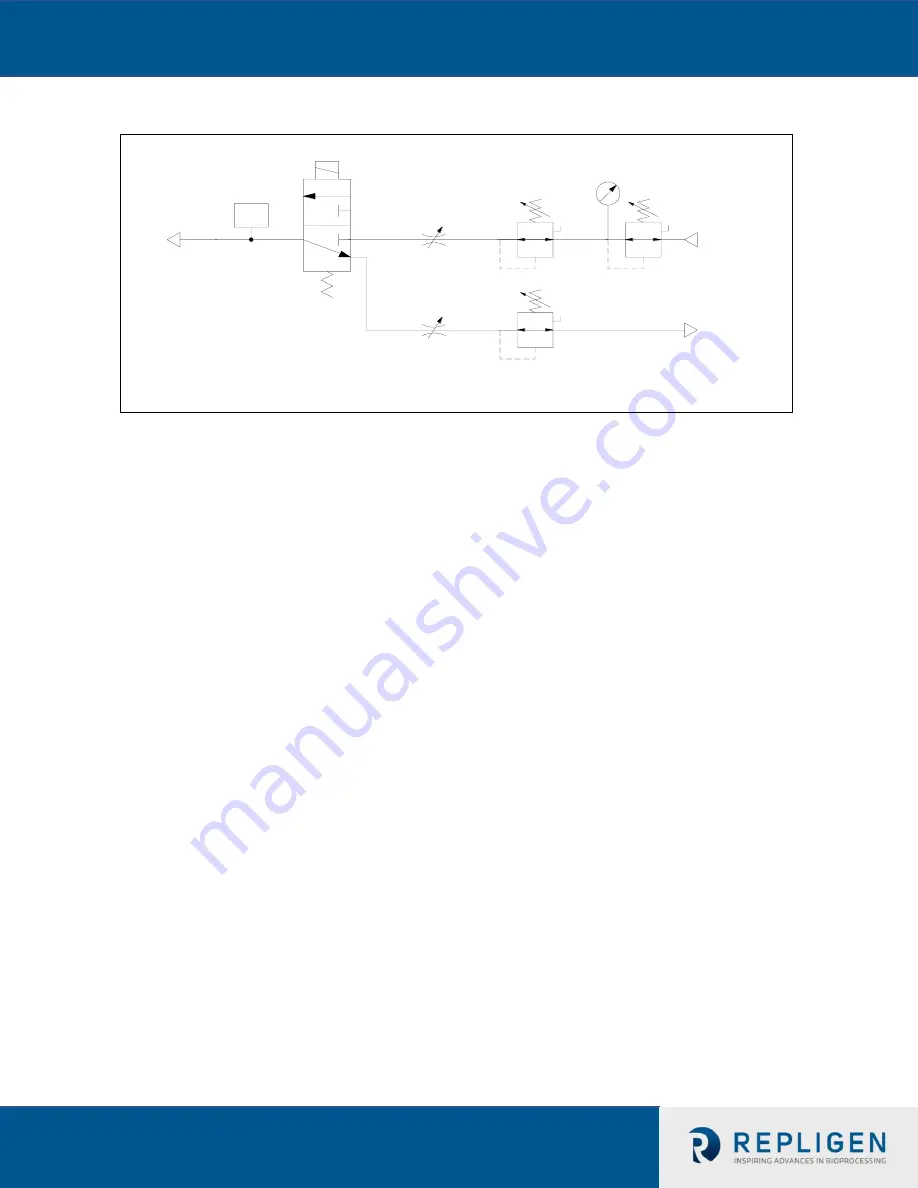
Figure 6.
Instrument Flow Control Schematic of C410v4B Controller
XCell™ ATF
System Flow control is achieved by regulating the pneumatic air flow to and
from the Diaphragm Pump; the pneumatic flow control is achieved with a two stage
control, by regulating its pressure and with a flow restrictor. Two Proportional Pressure
Regulators Valves, PRV1 and PRV2, are designed to make fine adjustments in pressure to
the air stream flowing from the manual pressure regulator to a flow restrictor. Two
automated flow restrictors, Proportional flow control Valves, PV1 and PV2, are designed to
make coarse adjustments in flow. Final flow control is achieved by Step changes in PV
orifice opening in combination with fine adjustments in the air flow stream pressure with
the PRV.
Adjustments in flow are based on the error difference between Calculated CT and Actual
CT. The proportional air pressure regulating valve, PRV1, and the exhaust pressure
regulating valve, PRV2, will be adjusted by the PLC based on the Error. The error will cause
pressures to be changed to affect the flow, positive or negative, respectively, to and from
the pump to match flow set point for the next cycle.
If the new value for PRV1 and/or PRV2 exceed their set pressure limits, (e.g. PRV1 0 to 30
psi, PRV2 0 to -14.5 psi), then, the respective PV1 and PV2 will adjust incrementally, (e.g.
by user defined increments (in the Basic Set Up Screen)), until the PRVs are back within
operational range.
6.2
Control Functional Algorithms
The C410v4B controller utilizes several algorithms to determine when the Diaphragm Pump
switches cycle direction.
The principal method is based on first detecting a steady state
pressure phase or “Driving Force” during each pump cycle followed by addition of a Switch
Offset, i.e. a pressure increment (or spike). A cycle change is executed when actual pump
pressure (as determined by P2) is equal or greater than the sum of Driving Force pressure and
Switch Offset pressure.


