MDW_700_EN_ANL_34-13.doc
21.08.2013
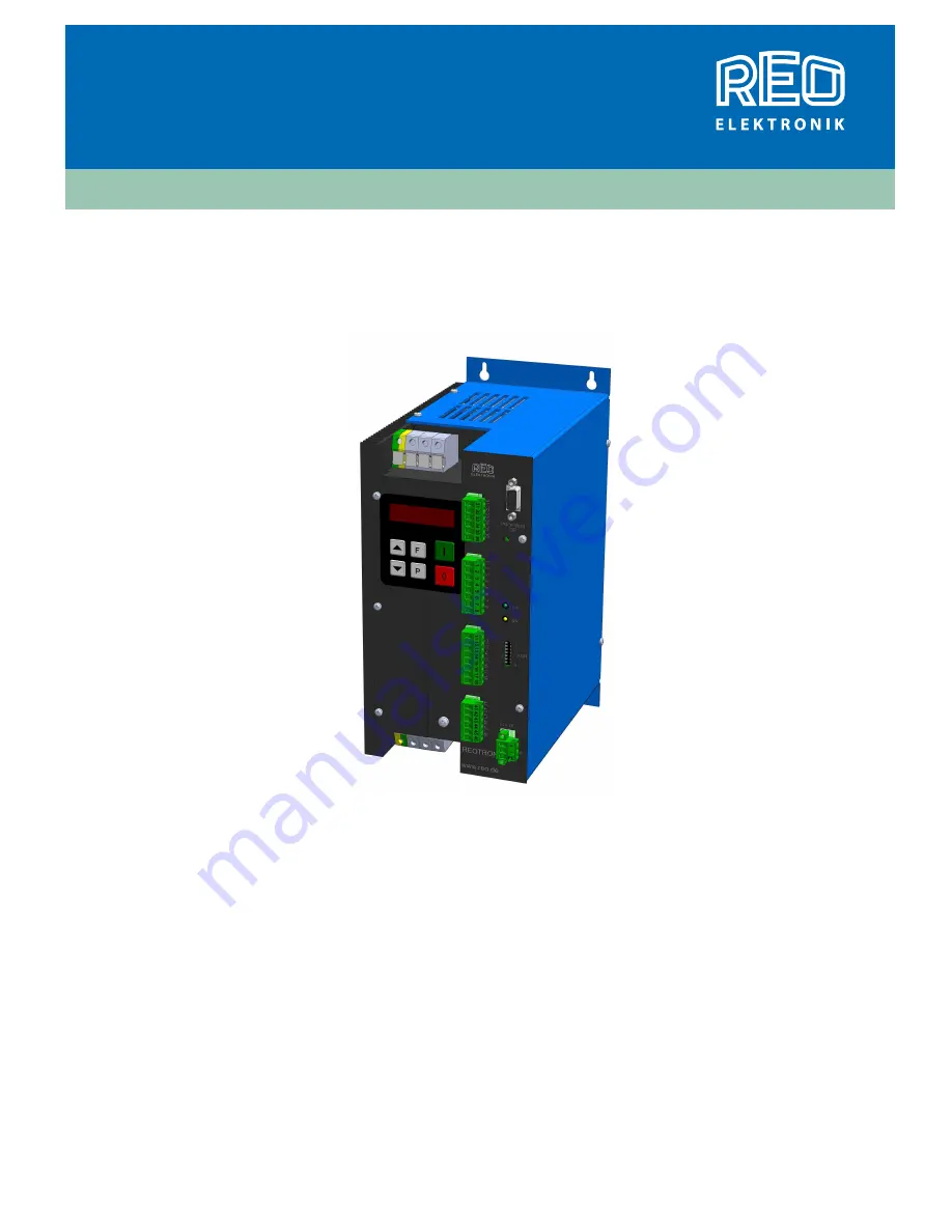
REOTRON
Electronic Power Controller
MDW 700
3-Phase-Thyristor Power Controller
Page 1: ...MDW_700_EN_ANL_34 13 doc 21 08 2013 REOTRON Electronic Power Controller MDW 700 3 Phase Thyristor Power Controller ...
Page 2: ...ice menu 13 9 2 2 Display effective values measured inside unit 13 9 3 Setting Up Procedures 14 9 4 Select Interface 14 9 5 Save current settings 15 9 6 Restore parameter settings 15 9 7 Software version 15 9 8 Hide parameter menus 15 10 0 Connection diagram 16 10 1 Connection details 17 11 0 Dimensions 18 12 0 Putting into service 22 12 1 Preliminaries 22 12 2 Measurements and Settings 22 12 3 Pu...
Page 3: ...rators and also for the protection of the described product and connected equipment Warning Hazardous Voltage Failure to observe can kill cause serious injury or damage Isolate from mains before installation or dismantling work as well as for fuse changes or post installation modifications Observe the prescribed accident prevention and safety rules for the specific application Before putting into ...
Page 4: ... a wide load resistance variation Rcold Rwarm are possible and an overloading of the unit is prevented Typical Applications Industrial Ovens Steam Generators Lighting Installations Infra Red Emitters Dryers Preheating Plants Air Conditioning Plant Tunnel Heaters Room Heating Equipment Fan Heating Systems Plastic Moulding Equipment Extruders 2 0 Construction The REOTRON MDW 700 thyristor controller...
Page 5: ... Serial RS 232 Fieldbus Profibus DP Fieldbus CAN Bus Fieldbus DeviceNet 3 1 Modes Phase angle control In the phase angle control mode the mains voltage half waves are more or less cut in function of the giv en set point This mode of operation is suitable for resistive inductive and resistive inductive loads The benefits with this mode of operation are the continuous adjustment the fine dosing and ...
Page 6: ... smaller bridge 100 Current regulation Microprocessor controller with PI Characteristics the P portion is adjustable externally by using the Key Pad The units maximum output current Rated Current is factory set Parameter setting Parameter Code Settings Output power P C 020 100 Set point voltage U Display or Set point current connection 3 u 4 C 020 100 or smaller bridge 100 Power regulation With po...
Page 7: ...nit or a connec tion made between terminals 32 and 33 by using a switch A permanent link between terminals 32 and 33 is used for operation without an external enable The firing pulses are inhibited whilst the enable input is not closed Start ramp Stop ramp This function reduces surges on the mains supply when the load is switched on and off Set point control min max The set point control character...
Page 8: ... U 0 5 V 22 kR External feedback I 0 5 V 22 kR Feedback monitor U or P 0 10 V DC 5 mA Feedback monitor I 0 10 V DC 5 mA Enable Contact 5 mA or 24 V DC 5 mA Faulty relay Change over contact 250 V 1 A Protection IP 20 Operating temperature 0 45 C Liquid temperature WK Type 25 C Input Liquid quantity H2O 6 ltr min Storing temperature 20 75 C Rel air humidity 93 without condensation and surface water ...
Page 9: ...W 700 200 230 400 6407 01 230 400 3x 200 REOTRON MDW 700 200 230 400 Profibus DP 6407 10 230 400 3x 200 REOTRON MDW 700 200 230 400 RS 232 6407 30 230 400 3x 200 REOTRON MDW 700 300 230 400 6409 01 230 400 3x 300 REOTRON MDW 700 300 230 400 Profibus DP 6409 10 230 400 3x 300 REOTRON MDW 700 300 230 400 RS 232 6409 30 230 400 3x 300 REOTRON MDW WK 700 115 230 400 6337 01 230 400 3x 115 REOTRON MDW ...
Page 10: ... in the user menus are protected A code must be entered to open the user menus There are different pass codes for each func tion group Setting adjustments are automatically saved upon leaving the programming mode or if no button is pressed for a period of 100 seconds 7 2 Adjustment Procedure All setting routines are commenced by pressing the programming button P The following diagram should clarif...
Page 11: ...wo upper vertical segments of the first digit illuminate Peak value limiter This is caused by a fault condition on either the load or by the externally generat ed effective value feedback signal The load impedance is too low for example or the effective value is too high The upper horizontal segment of the first digit illuminates Maximum control limit of the controller has been reached The unit ha...
Page 12: ...03 External Current set point 0 I E F I 0 003 Power regulation 0 I E F P 0 003 Full wave control 0 I F S P 0 003 Ready relay 0 I r b 0 003 Parameter Minimum Output Voltage without set point 0 100 U 0 020 Minimum Output Current without set point 0 100 I 0 020 Minimum Output Power without set point 0 100 P 100 020 Maximum Output Voltage Limit 25 100 u 100 020 Maximum Output Current Limit 25 100 i 10...
Page 13: ...rnal Set point 0 20 mA 0 10V 4 20 I External Set point 4 20 mA E F U 0 internal feedback voltage E F U I external feedback voltage Running mode E F P 0 Voltage Current regulation E F P I Power regulation set point F S P 0 Phase angle control F S P I Full wave control r b 0 Relay Status function r b I Relay Fault function E n 0 Invert Enable Off E n I Invert Enable On E F I 0 internal feedback curr...
Page 14: ...nt to the unit 9 2 2 Display effective values measured inside unit P Code 050 Display set point voltage Display set point power F P P P Running mode Display set point current P P Code 051 Display feedback voltage Display feedback power F P P P Running mode Display feedback current P ...
Page 15: ...rameter should be set to 0 P P P P P P P P P P P P P P P P P P Code 020 P P P P P P Min ouptput voltage without external set point Min output current without external set point Output voltage limit Umax Start ramp time Sec Running mode Output current limit Imax P Char current regulation Stop ramp time Sec Min output power without external set point P Char power regulation Output power limit Pmax P...
Page 16: ...ide parameter menus Code C 117 If Hd C I all parameter menus are hide Set Hd C to 0 again for change parameters Save current parameter settings Running mode P P P P Restore factory settings Running mode Restore user settings previously saved in C 143 P P P P P P Hd C 1 Hide menus Running mode P P P P Code 001 Version Date Running mode P P P P P P ...
Page 17: ... AC DC 0 10V DC 0 10V DC U U I ACTUAL VALUE OUTPUT RELAY STATUS LOAD I U PE L1 L2 L3 L2 W 1 2 3 4 5 6 7 8 33 32 31 15 16 17 18 11 12 13 14 41 42 43 V PE PE L1 U L3 FAILURE 44 45 46 3 AC 230 400 V 50 60 Hz I INTERFACE OPTION Interface 24 V DC CONTROL LOGIC 36 35 34 RELAY Fan MDW 50 300 U MDW 700 0 5V AC DC I 21 22 23 26 27 28 24 25 230 240V AC 50 60Hz T Fan test connector N T L ...
Page 18: ... 10V Voltage and current regulation Voltage regulation Current regulation 0 10 V 0 4 20 mA Set point power Pot 10 K 1 2 3 4 5 6 7 8 10V 10V 1 2 3 4 5 6 7 8 1 2 3 4 5 6 7 8 10V 10V 10V 10V Power regulation If using 4 20 mA signal set parameter 4 20 I in Menu C003 If using 4 20 mA signal set parameter 4 20 I in Menu C003 If using 4 20 mA signal set parameter 4 20 I in Menu C003 If using 4 20 mA sign...
Page 19: ...m 6 5 mm Option 11 0 Dimensions MDW 700 10 A 25 A MDW 700 50A 80A Attention connect the fan REOTRON MDW PROFIBUS DP 24V DC Us BA 1 ADR 8 PE 41 42 43 44 45 46 11 12 13 14 15 16 17 18 1 2 3 4 5 6 7 8 31 32 33 34 35 36 FOR CONTINUED FIRE PROTECTION REPLACE ONLY WITH SPECIFIED TYPE AND RATED FUSE DISCONNECT POWER INPUT BEFORE REPLACING FUSE I 0 P F Option PE L1 L2 L3 PE U V W 290 B 5 285 A 210 5 mm 5 ...
Page 20: ...415 430 255 210 231 12 Ø6 Ø6 Ø8 5 Ø8 5 1 6 2 7 3 8 4 9 5 L1 L2 L3 U V W DO NOT USE WITHOUT COVER PROFIBUS DP 24V DC Us BA 1 ADR 8 PE REOTRON MDW www reo de FOR CONTINUED FIRE PROTECTION REPLACE ONLY WITH SPECIFIED TYPE AND RATED FUSE DISCONNECT POWER INPUT BEFORE REPLACING FUSE P F I 0 PE 230V AC ...
Page 21: ...0 625 9 320 362 300 334 14 301 312 Schraube M10x40 933 Input 230V 50 60Hz REOTRON MDW L1 L2 L3 U V W www reo de P F I 0 1 2 3 U L1 V L2 W L3 Ø8 5 Ø8 5 Input air cooling Input air cooling Output air cooling 2 7 3 8 4 9 5 1 6 DP 24 PROFIBUS DP 24V DC ADR 1 8 U BA RESET PE PROFIBUS DP PE ...
Page 22: ...ater cooled Type A B MDW WK 115 160 250 350 400 380 MDW WK 450 600 550 530 REOTRON MDW L1 L2 L3 U www reo de P F I 0 U L1 V L2 W L3 Ø 9 0 Ø 19 0 202 212 A B 8 180 300 330 2 7 3 8 4 9 5 1 6 DP 24 PROFIBUS DP 24V DC ADR 1 8 U BA RESET PE PROFIBUS DP PE Ø 9 0 ...
Page 23: ...ly voltage and current sine curves are changed The output voltage and current must be measured with effective value meter true RMS 12 3 Putting into service without a proper load A thyristor can only be switched fired into a conducting state if the current level is sufficiently high enough It will only switch off if the current is lower than the threshold current every time the current goes throug...
Page 24: ...ould be suitable If direct on line switching is used i e by switching the thyristor controller without using the enable the rating of the contactors must be in accordance with AC3 13 3 Output Breaker A circuit breaker on the output of the thyristor controller should be avoided because it cannot operate without a load Current or voltage monitoring in the output of the thyristor controller must be u...
Page 25: ...nt it is to use correct earthing techniques 14 2 Control cables Control cables also are antennas that receive interference produced by other loads Signal cables that are run alongside power cables can generate voltage spikes through inductive and capacitive cross coupling Therefore control conductors should not be mixed with power cables in the same cable ducting If this cannot be avoided then shi...
Page 26: ...CNW 107 500 REOTRON MDW WK 700 450 CNW 107 500 Type weight in kg min cable cross section Power loss REOTRON MDW 700 10 4 1 5 mm 2 40 W REOTRON MDW 700 25 5 4 mm 2 100 W REOTRON MDW 700 50 8 5 16 mm 2 180 W REOTRON MDW 700 80 9 5 35 mm 2 310 W REOTRON MDW 700 110 11 50 mm 2 480 W REOTRON MDW 700 150 14 5 70 mm 2 540 W REOTRON MDW 700 200 16 95 mm 2 660 W REOTRON MDW WK 700 115 7 70 mm 2 500 W REOTR...
Page 27: ...REOTRON MDW 700 Operating instructions 26 ...
Page 28: ...l Spain REO ESPAÑA 2002 S A C Manuel Ventura i Campeny 21B local 9 E 08339 Vilassar de Dalt Barcelona Tel 34 937 509 994 Fax 34 937 509 995 E Mail info reospain com Internet www reospain com Switzerland REO ELEKTRONIK AG Im Halbiacker 5a CH 8352 Elsau Tel 41 0 52 363 2820 Fax 41 0 52 363 1241 E Mail info reo ch Internet www reo ch Turkey REOTURKEY ELEKTRONİK San ve Tic Ltd Şti Halil Rıfatpasa Mah ...