RSLM high accuracy linear encoder
Installation guide
M-6688-9043-02-B
TONiC
™
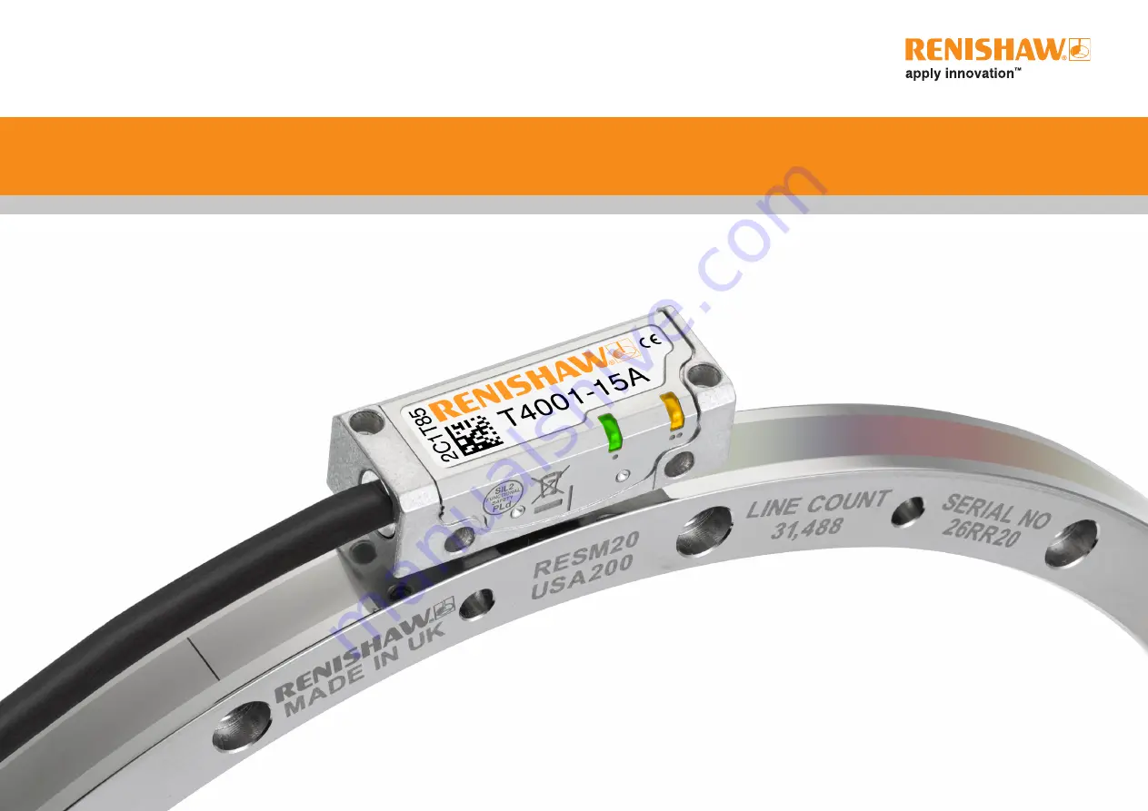
FS T40x1 RESM20 angle encoder system
Functional Safety installation guide and safety manual
Page 1: ...RSLM high accuracy linear encoder Installation guide M 6688 9043 02 B TONiC FS T40x1 RESM20 angle encoder system Functional Safety installation guide and safety manual...
Page 2: ...installation drawing B section 8 Select a mounting option 9 Taper mount method 9 Interference fit method 11 TONiC FS quick start guide 12 Cable connection 13 System connection Ti interface 13 System c...
Page 3: ...generates uses and can radiate radio frequency energy and if not installed and used in accordance with the instruction manual may cause harmful interference to radio communications Operation of this e...
Page 4: ...tem does not support low demand mode PFH per hour 8 41 10 9 1 38 10 8 3 49 10 8 Architectural constraints Type B HFT 0 SFF 96 Hardware safety integrity compliance Route 1H Systematic safety integrity...
Page 5: ...must be asserted if the phase shift is incorrect with reference to the safe position limit for the system see Output specifications on page 22 Following error check Following error is defined as the...
Page 6: ...9 The products comply with EU directives and comply with the following technical standards 2014 30 EU Electromagnetic compatibility EMC 2011 65 EU On the restriction of the use of certain hazardous su...
Page 7: ...Readhead only Acetone CH3 COCH3 Methylated Spirits Chlorinated Solvents Ring only 70 C 0 C Operating Humidity 95 relative humidity non condensing to IEC 60068 2 78 70 C 20 C TONiC RESM rings are non...
Page 8: ...n of ring increasing count 4 6 18 16 0 25 Yaw tol 0 4 A section Offset 1 75 0 5 B section Offset 3 25 0 5 3 7 5 3 29 22 2 off mounting holes M2 5 through counterbored 3 2 75 deep from alternative moun...
Page 9: ...6 30 T4021 52 10 30 00 57 9 000 57 35 37 04 47 6 30 57 25 37 00 75 11 840 75 40 55 04 65 6 30 T4011 75 30 55 00 100 15 744 100 30 80 04 90 6 30 100 20 80 00 103 16 200 103 20 80 04 90 6 30 103 00 80 0...
Page 10: ...CD DH 3 5 through N holes equally spaced on PCD DH M3 0 5 through A A DI DH DO Section A A 2 5 45 3 R0 5 7 6 5 Nominal external diameter mm Line count DO mm DI mm Mounting holes Readhead model DH mm N...
Page 11: ...aper diameter DT Diameter mm Roundness value mm TIR 115 0 025 150 to 225 0 050 300 0 075 Recommended surface finish Ra 1 2 NOTE It is recommended that the mounting surface is a turned rather than grou...
Page 12: ...to reduce the range of radial displacement When adjusting identify the screw location with the lowest radial displacement and tighten that screw aiming for the average of the highest and lowest indic...
Page 13: ...crew locations X X Tighten the screw with the lowest radial displacement so that it matches the average radial displacement whilst ensuring the maximum torque specified in the table is not exceeded X...
Page 14: ...en DOP interface ideally Blue Purple CALIBRATION Press and release the CAL button on the interface The CAL LED on the readhead will be single flashing Rotate the scale at slow speed 100 mm s without p...
Page 15: ...the readhead and the interface X X The customer is responsible for verifying the product function where the readhead to interface cable has been re terminated including the installation of extension...
Page 16: ...ng care not to touch the pins plug the connector into the socket in the interface ensuring correct orientation as shown 3 Refit the cover plate ensuring the cable ferrule is located in the recess on t...
Page 17: ...perating tolerances only apply where the correct readhead model conforms to the RESM size range Ensure readhead part number and RESM size range compatibility at the time of ordering and installation R...
Page 18: ...h 0 1 Roll 0 0 5 Rideheight 2 1 0 15 mm Optical centreline Green Orange Red Readhead set up LED status Green spacer Readhead set up Ensure that the ring readhead optical window and mounting face are c...
Page 19: ...cleanliness before repeating the calibration routine Step 2 Reference mark phasing X X Move the readhead back and forth over the reference mark until the CAL LED stops flashing and remains off The re...
Page 20: ...50 to 70 No Red Poor set up signal may be too low for reliable operation signal level 50 No Purple blank flashing Over signal system in error Yes Blue blank flashing Over speed system in error Yes Re...
Page 21: ...5 V Sense 5 0 V Power 12 0 V Sense 13 Incremental signals Analogue Cosine V1 9 1 Sine V2 10 2 Reference mark Analogue V0 3 11 Limits Open collector Vp 7 Vq 8 Set up Vx 6 Calibrate CAL 14 Shield Inner...
Page 22: ...16 20 10 10 6 75 2 70 1 35 0 675 0 270 0 135 0 068 0 027 0 013 12 10 9 4 50 1 80 0 900 0 450 0 180 0 090 0 045 0 018 0 009 10 10 8 10 4 05 1 62 0 810 0 405 0 162 0 081 0 041 0 016 0 0081 8 10 6 48 3 2...
Page 23: ...tput signals 0 V 5 V Readhead IMPORTANT The outer shield must be connected to the machine earth Field Ground The inner shield must be connected to 0 V at receiving electronics only Care should be take...
Page 24: ...being used 20 m 45 Output specifications Analogue output signals Incremental 2 channels V1 and V2 differential sinusoids in quadrature 90 phase shifted V1 V1 V2 V2 Bi directionally repeatable Differe...
Page 25: ...d IP40 Ti interface IP20 DOP interface IP30 Acceleration readhead Operating 500 m s 3 axes Shock system Non operating 500 m s 11 ms sine 3 axes Vibration system Operating 100 m s 55 Hz to 2000 Hz 3 ax...
Page 26: ...able disable Push and release 3 seconds AGC enable disable Push and hold during power Off On cycle Restore factory defaults Refer to readhead LED functionality chart for set up LED indications 48 32 9...
Page 27: ...S IN THIS DOCUMENT 2019 Renishaw plc All rights reserved Renishaw reserves the right to change specifications without notice RENISHAW and the probe symbol used in the RENISHAW logo are registered trad...