PI 200-3 installation guide
Document part number: H-1000-7542-03-B
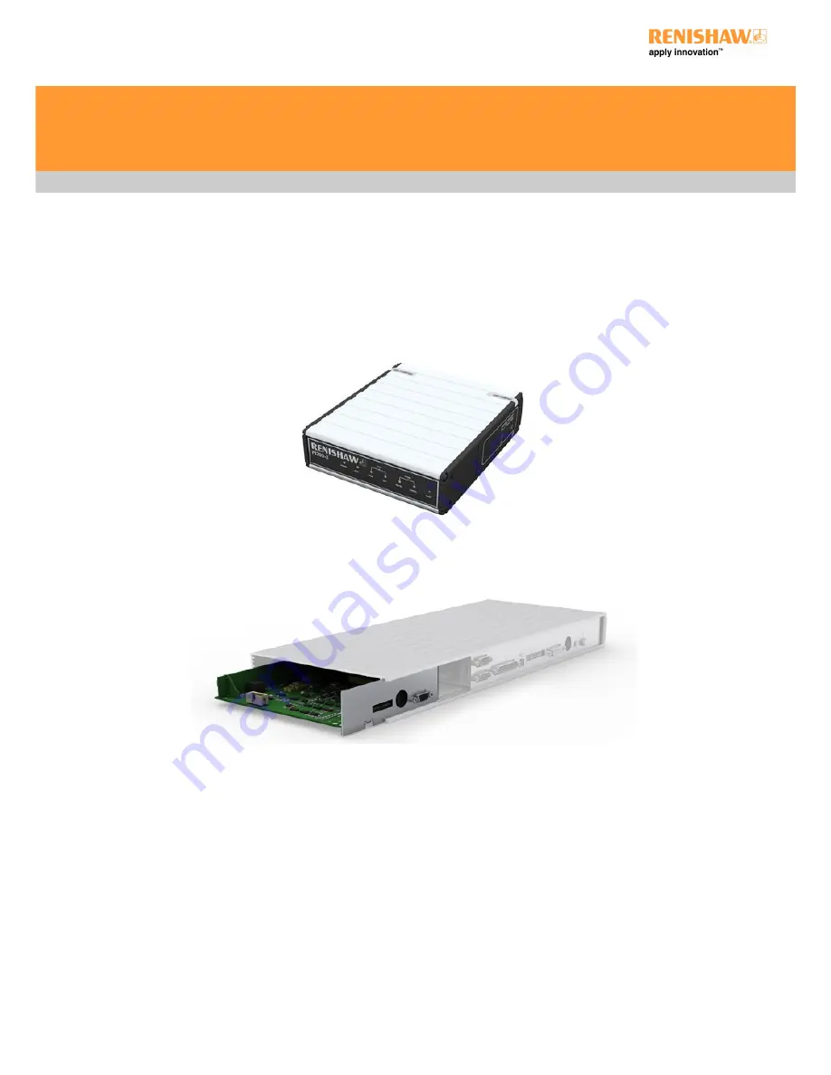
Stand alone unit
Card option to fit inside PHC10-3 PLUS
www.renishaw.com
Issued 01 2018
1
Page 1: ...PI 200 3 installation guide Document part number H 1000 7542 03 B Stand alone unit Card option to fit inside PHC10 3 PLUS PI 200 3 installation guide www renishaw com Issued 01 2018 1...
Page 2: ...f the Microsoft Corporation All trademarks and trade names are acknowledged WEEE The use of this symbol on Renishaw products and or accompanying documentation indicates that the product should not be...
Page 3: ...To aid end user recycling and disposal the materials used in the different components of the packaging are stated here Packaging component Material 94 62 EC code 94 62 EC number Outer box Corrugated...
Page 4: ...EU declaration of conformity Contact Renishaw plc or visit www renishaw com productcompliance for the full EU declaration PI 200 3 installation guide www renishaw com Issued 01 2018 4...
Page 5: ...this equipment in a residential area is likely to cause harmful interference in which case you will be required to correct the interference at your own expense Information to user 47CFR section 15 21...
Page 6: ...the supplied PSU If any additional means of isolation is required it must be specified and fitted by the machine manufacturer or installer of the product The isolator disconnection device must be site...
Page 7: ...2001 Indoor use IP30 no protection against water Altitude Up to 2000 m Operating temperature 0 C to 50 C Storage temperature 10 C to 70 C Relative humidity 80 maximum for temperatures up to 31 C Linea...
Page 8: ...removed and replaced as required without additional requalification by simply recalling the initial qualification data The probe sensor uses electronic strain sensing techniques that provide better fo...
Page 9: ...lone version A 5707 0100 The image below shows the PI 200 3 integrated card version A 5707 0200 that is intended to be used in conjunction with PHC10 3 PLUS for representation only PI 200 3 installati...
Page 10: ...SYNC SYNC is the real time PICS trigger signal used to trigger recording of the machine scale coordinates when taking a gauge point SYNC may also initiate the process of stopping and reversing CMM mo...
Page 11: ...SYNC and HALT signal timing for a TP200 gauge point SYNC and HALT signal timing for a gauge point when a kinematic probe is connected PI 200 3 installation guide www renishaw com Issued 01 2018 11...
Page 12: ...e debounce times are fixed Adaptive debounce Probe damped signal PDAMP During high speed position moves fast traverse it is necessary to reduce probe sensitivity to prevent vibration causing unwanted...
Page 13: ...the compensation is switched off If the stylus remains deflected for longer than ten seconds drift of the zero reference may occur The audible warning will sound after this period to indicate that th...
Page 14: ...wer on STOP Red PICS STOP asserted TYPE TP200 Green TP200 probe selected TYPE STD Green Kinematic probe selected PROBE SEATED Green ON probe armed seated OFF probe triggered or no probe connected PROB...
Page 15: ...ROBE SEATED Green ON probe armed seated OFF probe triggered or no probe connected PROBE DAMPED Yellow PICS PDAMP asserted Audible indicator The audible indicator has two functions The first is to prov...
Page 16: ...r SYNC LOW and SSR opens on trigger 5 Audible indicator UP DOWN No beep on trigger Indicator beeps on trigger 6 Debounce time Selects SYNC debounce time 7 Debounce mode Selects SYNC debounce mode 8 Ze...
Page 17: ...proximately 160 milliseconds when the probe triggers and SYNC is asserted When disabled the tone will activate only when the stylus has remained deflected for 10 seconds Switches 6 and 7 These switche...
Page 18: ...ements are used or where the CMM is inadequately isolated from the floor transmission of vibration from nearby machinery or vehicle traffic Trigger level 1 Is the highest sensitivity mode and provides...
Page 19: ...e moves when probe damped mode is asserted Switches 11 and 12 are used to select the nominal filter times Function of switches 11 and 12 Time delay Switch 11 Switch 12 2 ms DOWN DOWN 7 5 ms DOWN UP 15...
Page 20: ...DAMP 3 Ground 0 V 8 LEDOFF 4 LED anode 9 Probe signal ground 5 Probe signal input Shell Screen PICS output connector The PICS output connector is a 9 pin D type plug The pin numbers are illustrated an...
Page 21: ...Pin number Description 1 Not used 5 SSR 2 2 Screen 6 Not used 3 Not used 7 Not used 4 SSR 1 Shell Screen Stylus change rack SCR output connector The SCR200 stylus change rack is connected to the PI 2...
Page 22: ...y action push button or switch may be connected to pins 1 and 5 on the SCR200 miniature DIN connector on the rear panel If the connector is already in use for connection of a SCR200 stylus change rack...
Page 23: ...Weight 1 25 kg Mounting method 19 in rack or freestanding Mounting screws M5 6 mm maximum penetration Probe voltage open circuit 12 4 V Probe cable resistance Maximum 5 conductor Probe cable length Ma...
Page 24: ...ounting hardware Description Part number 1 3 1U blanking panel A 1018 0179 1 U rack mounting bracket A 1018 0189 PI 200 3 to PHC10 2 A 1018 0173 SCR200 stylus change rack Description Part number SCR20...
Page 25: ...1051 0417 Rotary adjustment module M8 M8 A 1047 7022 Rotary adjustment module autojoint to M8 A 1051 0679 Replacements Description Part number User s guide TP200 probe system English H 1000 5014 Inst...
Page 26: ...quired in final installation Inserting PI 200 3 card into PHC10 3 PLUS Remove the end panel of the PHC10 3 PLUS with a hex key and slide out the blanking plate Insert the PI 200 3 card ensuring that t...
Page 27: ...PI 200 3 installation guide www renishaw com Issued 01 2018 27...
Page 28: ...refer to the configuration switches section for more information If upgrading from TP2 measurement programs may need to be changed to suit the length of the TP200 which is 5 mm longer than the TP2 If...
Page 29: ...PI 200 3 interconnection with MH8 PI 200 3 interconnection with MIH head PI 200 3 installation guide www renishaw com Issued 01 2018 29...
Page 30: ...PHC10 2 and PI 200 3 interconnection with PH10M PI 200 3 installation guide www renishaw com Issued 01 2018 30...
Page 31: ...00 3 card with PHC10 3 PLUS interconnection with PH10T PLUS and SCR200 PI 200 3 with PHC10 3 PLUS interconnection with PH10M PLUS and SCR200 PI 200 3 installation guide www renishaw com Issued 01 2018...
Page 32: ...PI 200 3 card and PHC10 3 PLUS interconnection with PH10 PLUS and AC3 PI 200 3 and PHC10 3 PLUS interconnection with PH10 PLUS and AC3 PI 200 3 installation guide www renishaw com Issued 01 2018 32...
Page 33: ...R1 must be fitted to the autojoint connector on the probe head at the point of contact with the port lid SCR200 stylus change rack PI 200 3 and two SCR200 racks The miniature DIN connector on the base...
Page 34: ...PLM6 6 m 236 22 in A 1016 7564 Unterminated on end 4 PLM7 4 m 157 48 in A 1016 7563 Unterminated on end 4 PLM8 6 m 236 22 in A 1016 7677 4 PLM9 4 m 157 48 in A 1016 7678 5 PL25 300 mm 11 81 in A 1016...
Page 35: ...018 0179 Fit the panels using the M5 6 mm long screws provided Mounting PI 200 3 with PHC10 2 To mount a PI 200 3 next to a PHC10 2 controller in a 19 inch cabinet a bracket kit is required Renishaw p...
Page 36: ...be interfaces and system controllers without the need for additional hardware or software overheads on the CMM controller NOTE The order in which the system components are connected is important In pa...
Page 37: ...Periodically check the security of the mounting screws and electrical connectors Remove dust from the external surfaces with a dry lint free cloth PI 200 3 installation guide www renishaw com Issued...
Page 38: ...c jack plug PI 200 3 does not require a protective earth however an equipotential bonding point is provided on the rear panel for connection to the rest of the installation PI 200 3 interface is rated...
Page 39: ...ncrease the gauging The probe will not arm or the probe does not stay armed when the RESET button is released The probe LEDs are always OFF PI 200 3 indicators Possible causes Remedy STD LED is ON SEA...
Page 40: ...s Remedy DAMPED LED is OFF SEATED LED operates normally The stylus is too large or too heavy There is excessive vibration from the CMM Use stylus arragements within recommendations Check the CMM s air...
Page 41: ...ails please visit our main website at www renishaw com contact Renishaw plc New Mills Wotton under Edge Gloucestershire GL12 8JR United Kingdom T 44 0 1453 524524 F 44 0 1453 524901 www renishaw com c...