


Renesas RYZ012x1 RYZ012A1 Pmod™ Expansion Board – Quick Start Guide
R21QS0002EG0100 Rev.1.00
Page 5 of 9
Feb.14.22
1. Product Overview
This Pmod™ expansion board provides a quick and easy way to interface with the RYZ012A1 module.
More information about this module can be found on the Renesas website:
2. Pmod™ Interface
2.1 Overview
The RYZ012A1 Bluetooth Low Energy Pmod™ expansion board provides an interface using a 12-pin
Digilent Pmod™ compatible connector (CN1).
This provides access to:
•
A high-speed UART interface (MSTR_CTS)
•
An SPI interface (MSTR_SS)
•
A mode reset pin (NRST)
•
VDD and GND connections for module power
Pmod™ is registered to Digilent Inc. and its specification can be found at the link below:
https://digilent.com/reference/pmod/start
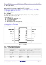
2.2 Pin Diagram
Figure
1
. Pin Diagram
2.3 Pin Descriptions and Directions
Table 1.
Pin Descriptions and Directions
Pin Number
Pin Name
Description
Direction
1
MSTR_CTS/SS
SPI SS / UART CTS
UART CTS output, or SPI SS output
2
MSTR_TX
SPI DI / UART RX
TX Input to Pmod
3
MSTR_RX
SPI DO / UART TX
RX Output from Pmod
4
MSTR_CK
SPI CK / UART RTS
CLK input to Pmod
5
GND
GND
NA
6
VDD
3.3 V
NA
7
GPIO_IRQ
INTERRUPT
Input
8
NRST
RESET
Input