R01UH0823EJ0100 Rev.1.00
Page 150 of 1823
Jul 31, 2019
RX23W Group
7. Option-Setting Memory (OFSM)
Note 1. The value of the blank product is FFFF FFFFh. This register is set to a specified value after programming of the flash memory
with the user program.
The OFS0 register is allocated in the ROM. Set this register at the same time as writing the program. After writing to the
OFS0 register once, do not write to it again.
When erasing the block including the OFS0 register, the OFS0 register value becomes FFFF FFFFh.
The setting in the OFS0 register is ignored in boot mode, and this register functions similarly when it is set to FFFF
FFFFh.
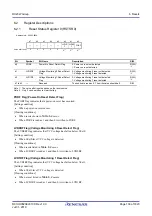
IWDTSTRT Bit (IWDT Start Mode Select)
This bit selects the mode in which the IWDT is activated after a reset (stopped state or activated in auto-start mode).
When activated in auto-start mode, the OFS0 register setting for the IWDT is effective.
IWDTTOPS[1:0] Bits (IWDT Timeout Period Select)
These bits select the timeout period, i.e. the time it takes for the down-counter to underflow, as 128, 512, 1024, or 2048
cycles of the frequency-divided clock set by the IWDTCKS[3:0] bits. The time (number of IWDT-dedicated clock
cycles) it takes to underflow after a refresh operation is determined by the combination of the IWDTCKS[3:0] bits and
IWDTTOPS[1:0] bits.
For details, see
section 31, Independent Watchdog Timer (IWDTa)
IWDTCKS[3:0] Bits (IWDT Clock Frequency Division Ratio Select)
These bits select, from 1/1, 1/16, 1/32, 1/64, 1/128, and 1/256, the division ratio of the prescaler to divide the frequency
of the IWDT-dedicated clock. Using the setting of these bits together with the IWDTTOPS[1:0] bit setting, the IWDT
counting period can be set from 128 to 524288 IWDT-dedicated clock cycles.
For details, see
section 31, Independent Watchdog Timer (IWDTa)
IWDTRPES[1:0] Bits (IWDT Window End Position Select)
These bits select the position of the end of the window for the down-counter as 0%, 25%, 50%, or 75% of the value being
b19, b18
WDT Timeout Period Select
b19 b18
0 0: 1024 cycles (03FFh)
0 1: 4096 cycles (0FFFh)
1 0: 8192 cycles (1FFFh)
1 1: 16384 cycles (3FFFh)
R
b23 to b20
WDT Clock Frequency
Division Ratio Select
b23 b20
0 0 0 1: Divide-by-4
0 1 0 0: Divide-by-64
1 1 1 1: Divide-by-128
0 1 1 0: Divide-by-512
0 1 1 1: Divide-by-2048
1 0 0 0: Divide-by-8192
Settings other than above are prohibited.
R
b25, b24
WDT Window End Position
Select
b25 b24
0 0: 75%
0 1: 50%
1 0: 25%
1 1: 0% (No window end position setting)
R
b27, b26
WDT Window Start Position
Select
b27 b26
0 0: 25%
0 1: 50%
1 0: 75%
1 1: 100% (No window start position setting)
R
b28
WDT Reset Interrupt Request
Select
0: Non-maskable interrupt request is enabled
1: Reset is enabled
R
b31 to b29
—
Reserved
When reading, these bits return the value written by the
user. The write value should be 1.
R
Bit
Symbol
Bit Name
Description
R/W


