CHAPTER 4 DESCRIPTION OF FUNCTIONS
User’s Manual S19262EJ3V0UM
42
4.6.1 Transmission data modulation by IR encoder
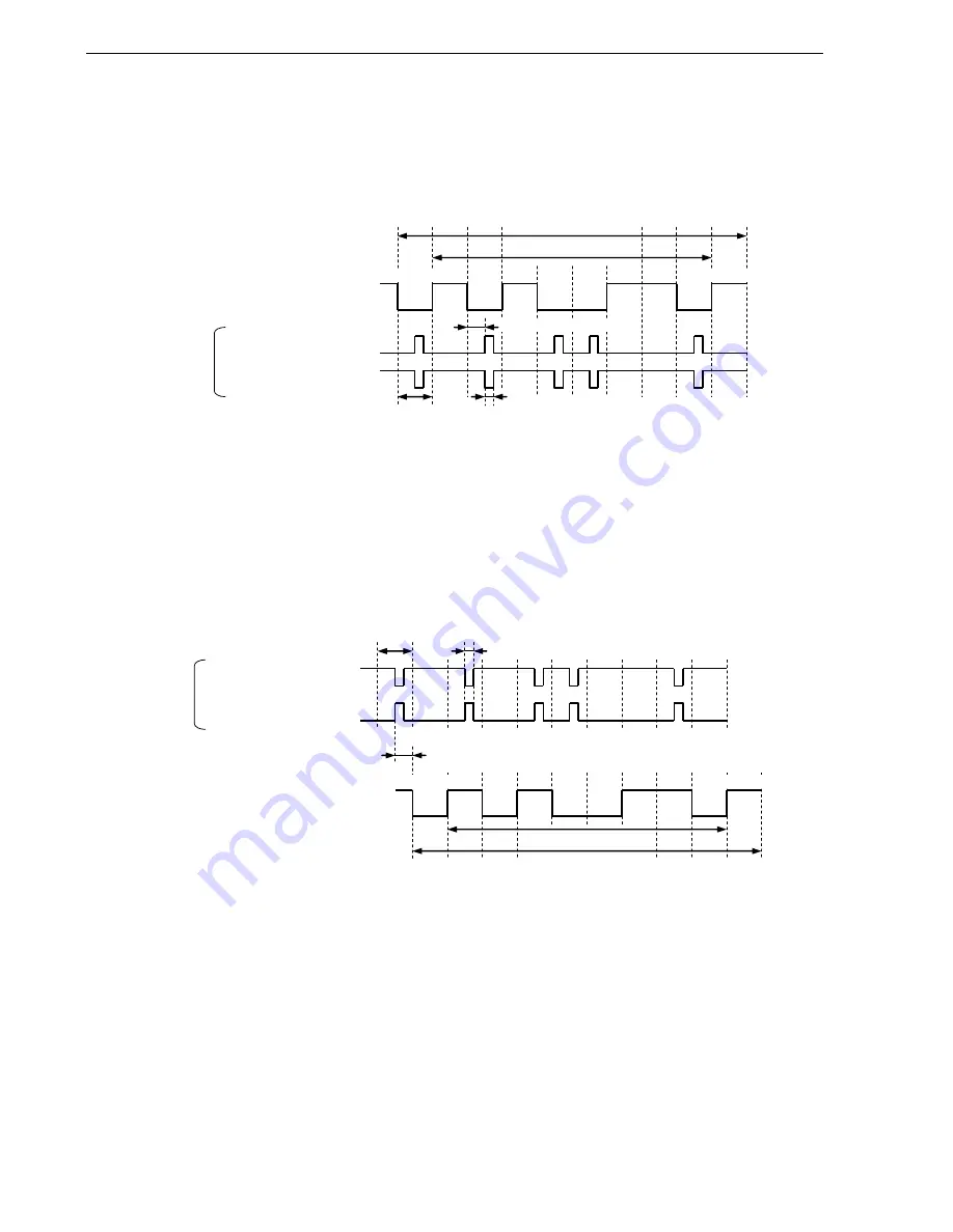
When the transmitted data value is 0, a pulse with the width of the baud rate cycle multiplied by 3/16 is output. The
polarity of transmission pulses can be selected by using bit 1 (IR_TXPSEL) of the IRCR0 register.
Figure 4-2. Transmission Data Modulation Example
0
1
Encoder input
0 1 0 0 1 1 0 1
Stop
Start
Data bit
UART frame
Bit time
Pulse width (3/16 bit time)
IRCR (IR_TXPSEL) = 0
IRCR (IR_TXPSEL) = 1
UARTx_SOUT
(output)
1/2 bit time
4.6.2 Reception data demodulation by IR decoder
The IR decoder outputs 0 if the input pulse width is valid (value set to the PULSE_WIDTH[7:0] bits of IRCR1
register) or longer; otherwise it outputs 1. The polarity of reception pulses can be selected by using bit 5
(IR_RXPSEL) of the IRCR0 register.
Figure 4-3. Reception Data Demodulation Example
0
1
Decoder output
0 1 0 0 1 1 0 1
Stop
Start
Data bit
UART frame
Bit time
Pulse width: IRCR1 (PULSE_WIDTH[7:0]) is used to set the
width of pulses to detect as valid pulses.
IRCR (IR_RXPSEL) = 0
IRCR (IR_RXPSEL) = 1
UARTx_SIN
(input)
Delay < (3 + PULSE_WIDTH[7:0] value) CLK @ XIN
+ 4/16 bit time
Table 4-2 lists examples of valid pulse width settings (PULSE_WIDTH[7:0] of the IRCR1 register). In this table, the
values of PULSE_WIDTH[7:0] are expressed in decimal notation. This table only presents some examples of the
desired valid reception pulse width and XIN clock frequency values. Change the values according to the user system.


