Renegade Labs Gray|328
The display changes to indicate your selection. Refer above to
Figure 45 which shows Fader 1 with Input A, channels 1 and 2
assigned to it.
Clearing an input assigned to a fader
1.
Press the Select button for the desired fader.
2.
Press ASSIGN to display the Fader Assignment Menu
3.
Choose CLEAR to clear the input.
4.
Deselect the Select button to end the fader de-assignment process.
Setting Up Fader Output Routing
Output routing is the process of choosing which Program output buses a
fader’s stereo output will be routed to when the PGM or PST button for
the fader is selected.
To change a fader’s output routing:
1.
Press the Select button above the desired fader to display the Route
Menu.
Note
If the selected fader has no inputs assigned to it, you will be taken to the
Fader Assignment Menu for input assignment. The fader must have an
input assigned to it in order to perform output routing. See “Assigning
inputs to a fader” on page 53 for more information.
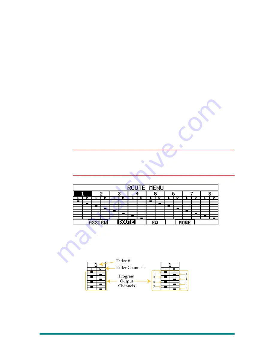
Figure 57. Route Menu
The example above shows Fader #1 selected (darkened). The program
outputs to which the fader is routed are indicated in the detail, illustrated
in the following:
Figure 58. Route Menu Detail
2.
Using the Multi-Function Keypad, select the output buses to which the
fader should be assigned.
Remember that each fader is a stereo fader, and thus has a left and
right channel to route. Both channels are assigned together.
Page 56
Making Fader Assignments


