User Manual
FROG-6
UM-0007-REV.06
Page 14
3
OPERATING PARAMETERS
3.1
Introduction
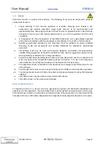
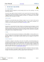
The FROG-6 has been designed to ensure passenger safety even when operating in the most
demanding conditions.
There are a large number of factors that affect the safe conduct of all marine personnel transfers.
These include: crew skill and experience, met-ocean conditions, landing area, vessel station keeping
capability and response to sea conditions, visibility, line of sight, etc. A combination of many factors
will determine the risk involved in a transfer:
Vertical impacts
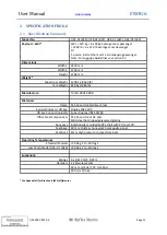
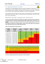
Passengers are protected during heavy landings at speeds of up to 4.0 m/s (13.1 ft/s) by the
properties of the feet, frame and spring-mounted seat base. These protect passengers up to
currently recommended operating limits as detailed in
; Table 1.
Lateral impacts
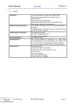
Passengers are also protected from lateral impacts by the framework and seat harnesses. Lateral
impacts are only likely to arise due to sway caused by off-lead when lifting and fast slewing. The
passengers will be protected up to the 2 m/s (6.5 ft/s) maximum expected impact speed. The central
column may deform on lateral impact and there may be damage to other components and therefore
the equipment must be inspected after any impact.
Stability
The unit has a low centre of gravity and a tripod base, providing stability on uneven surfaces or on a
pitching / rolling vessel. The polyurethane coated landing feet are also a non-skid design keeping
grip on deck surfaces. The static angle of stability has been tested to 35 degrees, for a load of 1-6
passengers.
Control of Hoist Line
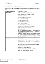
The FROG-6 is designed to stay firmly on the deck of the transfer vessel whilst passengers are
entering or leaving the capsule. The Crane Operator must maintain slack in the line upon landing to
allow for the vessel movement. The recommended limits in this section are based on the use of the
standard FROG-6 sling length of 30 ft (9 m). For the use of shorter slings an additional risk
assessment combined with dry runs should be performed to establish safe operational routines and
weather conditions. (See Section
It is important that all environmental and operational factors are taken into account in the pre-
transfer risk assessment. Assessing the impact of these factors on operational risk must be done by
Competent Personnel experienced in use of the equipment and the local conditions.
Summary of Contents for FROG-6 HC6-01 620
Page 62: ...User Manual FROG 6 UM 0007 REV 06 Page 62...
Page 63: ...User Manual FROG 6 UM 0007 REV 06 Page 63...
Page 64: ...User Manual FROG 6 UM 0007 REV 06 Page 64...
Page 65: ...User Manual FROG 6 UM 0007 REV 06 Page 65...
Page 66: ...User Manual FROG 6 UM 0007 REV 06 Page 66...
Page 67: ...User Manual FROG 6 UM 0007 REV 06 Page 67...
Page 68: ...User Manual FROG 6 UM 0007 REV 06 Page 68...
Page 69: ...User Manual FROG 6 UM 0007 REV 06 Page 69...
Page 70: ...User Manual FROG 6 UM 0007 REV 06 Page 70...
Page 71: ...User Manual FROG 6 UM 0007 REV 06 Page 71...
Page 72: ...User Manual FROG 6 UM 0007 REV 06 Page 72...
Page 73: ...User Manual FROG 6 UM 0007 REV 06 Page 73...
Page 74: ...User Manual FROG 6 UM 0007 REV 06 Page 74...
Page 75: ...User Manual FROG 6 UM 0007 REV 06 Page 75...
Page 76: ...User Manual FROG 6 UM 0007 REV 06 Page 76...
Page 77: ...User Manual FROG 6 UM 0007 REV 06 Page 77...
Page 78: ...User Manual FROG 6 UM 0007 REV 06 Page 78...
Page 81: ...User Manual FROG 6 UM 0007 REV 06 Page 81 12 2 Decals Vinyl Stickers Located on Buoyancy Units...
Page 82: ...User Manual FROG 6 UM 0007 REV 06 Page 82...
Page 83: ...User Manual FROG 6 UM 0007 REV 06 Page 83...
Page 84: ...User Manual FROG 6 UM 0007 REV 06 Page 84 12 3 Decal Operating Instructions Located on Seat...
Page 88: ...User Manual FROG 6 UM 0007 REV 06 Page 88 Link to Index Link to Index...
Page 93: ...User Manual FROG 6 UM 0007 REV 06 Page 93...
Page 94: ...User Manual FROG 6 UM 0007 REV 06 Page 94...
Page 95: ...User Manual FROG 6 UM 0007 REV 06 Page 95...

