6 Function overview
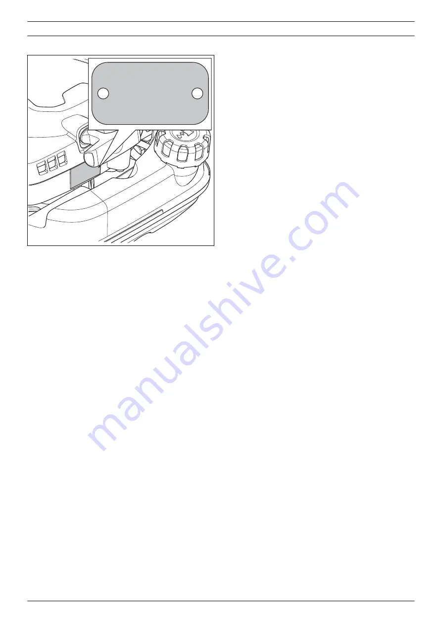
6.1 Type plate and product serial number
RedMax CHTZXXXX
s/n 20XX XXXXXXX
XXX XX XX-XX
Husqvarna AB
Huskvarna, Sweden
12 - Function overview
1351 - 002 - 25.11.2020
Page 1: ...Workshop manual CHTZ60 English 1351 002 25 11 2020...
Page 2: ...0 6 Function overview 6 1 Type plate and product serial number 12 7 Repair instructions 7 1 Product overview for repair instructions 13 7 2 To clean and examine the product parts 14 7 3 Starter 14 7 4...
Page 3: ...tand the manual 1 3 Revisions Changes to the product can cause changes to the maintenance work and spare parts Separate information is sent out for each change Read the manual together with all receiv...
Page 4: ...se the product correctly Read the operator s manual carefully and make sure that you understand the instructions before you use this product Stop Use a protective helmet in locations where objects can...
Page 5: ...kout and the throttle trigger X Examine the engine the fuel tank and the fuel lines for leaks X Tighten nuts and screws X Examine the fuel filter for contamination and the fuel hose for cracks and oth...
Page 6: ...a 4 1 Servicing data Lubricate with 2 stroke oil Lubricate with grease T27 3 4 Nm T27 3 4 Nm T27 3 4 Nm T27 5 8 Nm T27 3 4 5 Nm T27 3 4 5 Nm T27 1 5 2 5 Nm T27 2 3 Nm T27 2 3 Nm 6 Servicing data 1351...
Page 7: ...T27 6 8 Nm T27 6 9 Nm 10 15 Nm 8 mm 6 9 Nm T27 4 6 Nm T27 3 5 Nm 1351 002 25 11 2020 Servicing data 7...
Page 8: ...T27 1 5 2 5 Nm T27 4 5 5 5 Nm T27 6 8 Nm TXX 6 8 Nm 16 mm 10 12 Nm T27 4 6 Nm T27 8 10 Nm T27 3 4 Nm T27 3 4 Nm T27 2 5 3 Nm 10 12 Nm 8 Servicing data 1351 002 25 11 2020...
Page 9: ...T27 6 9 Nm T27 3 5 Nm 8 mm 6 9 Nm 8 mm 6 9 Nm 8 mm 6 9 Nm 8 mm 6 9 Nm T27 3 5 Nm 1351 002 25 11 2020 Servicing data 9...
Page 10: ...5 Servicing tools 5 1 Servicing tools 0 5 m m 0 3 1 2 3 4 5 6 7 8 9 10 11 12 13 14 15 17 18 19 16 20 10 Servicing tools 1351 002 25 11 2020...
Page 11: ...e fuel filter out of the fuel tank 502 50 83 01 10 Removal tool for the piston pin To remove the piston pin 505 38 17 05 11 Air gap gauge 0 3 mm To measure the distance between the flywheel and the ig...
Page 12: ...6 Function overview 6 1 Type plate and product serial number RedMax CHTZXXXX s n 20XX XXXXXXX XXX XX XX XX Husqvarna AB Huskvarna Sweden 12 Function overview 1351 002 25 11 2020...
Page 13: ...erview for repair instructions 5 3 1 6 2 4 9 12 13 7 11 10 8 14 1 Starter unit 2 Muffler 3 Spark plug 4 Flywheel 5 Ignition module 6 Air filter 7 Fuel tank 8 Carburetor 9 Rear handle 10 Gearbox 1351 0...
Page 14: ...rews and the starter unit 2 Install in the opposite sequence 7 3 2 To disassemble the starter unit WARNING Use protective glasses The recoil spring can eject from the starter pulley and cause injury 1...
Page 15: ...ged Make sure that the starter pawl springs on the starter pawl assembly are attached correctly and move freely Lubricate the starter pawls on the starter unit Lubricate the starter spring 7 3 4 To in...
Page 16: ...starter housing Put the free end of the recoil spring into the dedicated slot B on the hub of the starter housing 7 Install the drive disc spring C E D C 8 Lubricate the drive disc spring with cold re...
Page 17: ...l the air filter 1 Turn the knob counterclockwise and remove the air filter cover 2 Remove the air filter 3 Install in the opposite sequence 7 5 2 To clean and examine the air filter WARNING Use prote...
Page 18: ...g tools on page 10 CAUTION Make sure that the piston stop does not go into the exhaust port There is a risk of engine damage 5 Remove the nut 6 Attach the flywheel removal tool to the crankshaft refer...
Page 19: ...the flywheel in position on the crankshaft 5 Install the piston stop in the spark plug hole Refer to Servicing tools on page 10 6 Install the nut and tighten the nut with the correct torque Refer to S...
Page 20: ...cal data on page 50 Replace the spark plug if it is necessary 7 8 2 To do a spark test 1 Remove the spark plug from the cylinder 2 Connect the spark plug to the spark plug cap 3 Make sure that the sto...
Page 21: ...show more than 1000 with the stop switch in the stop position Replace the stop switch if the resistance is less than 1000 b The ohmmeter must show more than 0 1 with the stop switch in the start posi...
Page 22: ...p with soap and water or equivalent to make it easier to push it into position 8 Push the cable into the spark plug cap 9 Use the pliers or a screwdriver to align the spring with the hole in the spark...
Page 23: ...er to To remove and install the starter unit on page 14 7 8 7 To remove and install the ignition module 1 Remove the starter unit Refer to To remove and install the starter unit on page 14 2 Remove th...
Page 24: ...ket G G H I 8 Make a note of how the fuel hoses H and I are connected 9 Disconnect the fuel hoses and remove the carburetor 10 Install in the opposite sequence 7 9 2 To disassemble and assemble the ca...
Page 25: ...retor housing 11 Do a pressure test of the carburetor Refer to To do a pressure test of the carburetor on page 25 12 Assemble in the opposite sequence 7 9 3 To do a pressure test of the carburetor 1 R...
Page 26: ...ses the engine speed The idle speed screw controls the throttle position Turn the idle speed screw clockwise gives fast idle speed turn it counterclockwise gives lower idle speed The high speed jet an...
Page 27: ...t H 4 Install in the opposite sequence 7 10 2 To remove and install the throttle handle 1 Remove the carburetor Refer to To remove and install the carburetor on page 23 2 Disconnect the short circuit...
Page 28: ...uches the safety catch C Push in the safety catch with a small screwdriver and turn the rear handle turn more A C B 3 Push up the flange D with a small screwdriver and remove the handle holder E from...
Page 29: ...9 Remove the throttle cable from the throttle trigger 10 Make a note of the position of the recoil spring 11 Remove the throttle trigger throttle trigger lockout and the recoil spring 12 Make a note...
Page 30: ...ing unit 7 Examine the cutting unit for damage and wear Replace damaged parts 8 Examine the sharpness of the blades Sharpen the blades if it is necessary 9 Install in the opposite sequence 7 12 Clutch...
Page 31: ...vent damage to the clutch assembly 10 Disassemble the clutch shoes from the hub with a screwdriver 11 Assemble in the opposite sequence 7 12 2 To disassemble and assemble the gearbox 1 Remove the cutt...
Page 32: ...install the clutch drum 1 Disassemble the gearbox Refer to To disassemble and assemble the gearbox on page 31 2 Put a pin through the holes A in the gearbox housing and the clutch drum to prevent revo...
Page 33: ...nstall the muffler on page 17 8 Remove the air filter Refer to To remove and install the air filter on page 17 9 Remove the air filter housing and the carburetor Refer to To remove and install the car...
Page 34: ...the cylinder cover 10 Remove the heat shield 11 Remove the 2 screws the cylinder and the cylinder gasket 12 Put a cloth above the crankcase opening below the piston 34 Repair instructions 1351 002 25...
Page 35: ...piston and the piston pin bearing 15 Remove the snap rings and the piston pin Remove the piston Remove the crankshaft bearing seal A and the needle bearing B from the piston rod A A B 16 Remove the p...
Page 36: ...examine the piston Make sure that the piston pin bearing is not damaged Make sure that the piston pin does not have damages on the surface against the bearing Make sure that the piston ring can move...
Page 37: ...ston 1 Lubricate the needle bearing with two stroke oil and put it into the connecting rod Make sure that the needle bearing moves freely in the connecting rod A A B 2 Install the piston The arrow at...
Page 38: ...mpress the piston ring Carefully push the piston into the cylinder opening Tighten the 2 screws to the specified torque Refer to Servicing data on page 6 8 Install the remaining parts in the opposite...
Page 39: ...shaft ball bearing 3 Remove the gasket and clean remaining gasket material from the surfaces 4 Use a screwdriver or equivalent to remove the sealing ring on each crankcase half CAUTION Remove the seal...
Page 40: ...ncrease the temperature of the crankcase halves to 120 C with a hot air gun 8 Use the removal tool for the ball bearings to remove the ball bearings from the crankcase halves a Flywheel side 40 Repair...
Page 41: ...g rod If there are marks or discoloration in the groove of the bearing replace the crankshaft Examine the crankshaft bearing There must be no radial play in the connecting rod Make sure that there is...
Page 42: ...earing refer to Servicing tools on page 10 with a rubber hammer until the ball bearing is in position Make sure that the ball bearing are against the snap ring a Flywheel side b Clutch side 3 Put the...
Page 43: ...ankshaft into the ball bearing 5 Install the gasket to the clutch side of the crankcase half Lubricate the crankshaft pin with some drops of oil and move the crankcase half on the clutch side into pos...
Page 44: ...all the air filter on page 17 4 Remove the transparent fuel hose A from the carburetor and connect it to the pressure tester A 5 Tighten the fuel tank cap Make sure that the are no leaks around the bu...
Page 45: ...re that the connection neck of the fuel filter is put as far as possible into the fuel hose 6 Put the fuel filter in the tank as shown in the illustration Note The illustrations show a different tank...
Page 46: ...alve The needle valve is worn Object in the needle valve guide Idle speed low speed The engine does not operate on idle speed The stop screw for the throttle does not operate correctly Blocked fuel fi...
Page 47: ...control diaphragm is damaged The needle valve is worn Object in the needle valve guide The engine stops when idling The stop screw for the throttle does not operate correctly Blocked fuel filter Bloc...
Page 48: ...valve guide Increasing and decreasing speed The engine does not increase speed Blocked fuel filter Blocked fuel hose Air in fuel pipes Vacuum pulse leakage Blocked vacuum pulse pipe Loose screws on th...
Page 49: ...Increasing and decreasing speed Can not increase speed Defective heat insulation seal 1351 002 25 11 2020 Troubleshooting 49...
Page 50: ...EN ISO 10517 m s2 Front Rear mm s2 4 4 4 3 Blades Type Double sided Cutting length mm 600 Cutting speed cuts min 4400 1 Noise emissions in the environment measured as sound power LWA in conformity wit...
Page 51: ...1351 002 25 11 2020 Technical data 51...
Page 52: ...www redmax com 114 19 79 26 2020 12 01...