background image


 Red

MAX


Subscriber Modem


User Manual


70-00057-01-01-DRAFT 

Proprietary Redline Communications © 2006

 December 

13, 

2006 

Page 30 of 60


Chapter 

5


5

5


C

C

L

L

I

I


C

C

o

o

m

m

m

m

a

a

n

n

d

d

s

s


This section describes the subscriber CLI commands. 

5.1 Introduction 

The subscriber can be configured using a Telnet connection established through 
the subscriber Ethernet port or over the wireless interface from the base station. 
The CLI can not be used to setup service flows. All service flows will be setup by 
the base station. 

5.2 CLI 

Modes 

The subscriber CLI interface supports several modes of operation. From root 
mode you can display a list of all user modes, reboot the subscriber system, and 
logout from the Telnet session. Monitor mode provides a dynamic display of the 
current system statistics, updated each few seconds. Configuration modes allow 
you to view and adjust the subscriber network and wireless settings. 

5.2.1 Telnet 

Connection 

Telnet Login 

Type 'telnet' followed by the IP address of the subscriber system, depress ENTER, 
and enter the account and password when prompted. The subscriber supports two 
separate user accounts: 

Table 8: CLI - Command Groups 

Account  Password  Description 
admin admin  Full 

system 

control 

user2 

user2 

Read-only with some functional restrictions (not allowed to use 

the 'set' command). 

guest 

guest 

Same as user2. 


Telnet Logout 

To exit from the Telnet session, you must be in the root directory. Go to the root 
directory by typing: 

Exit [ENTER] or CTRL-Z (hold down the CTRL key and depress Z) 

Exit from a CLI session by typing: 

logout [ENTER] 

The system prompts for logout confirmation. Depress 'Y' to complete the logout 
process. 

Summary of Contents for RedMAX SU-I

Page 1: ...70 00057 01 01 DRAFT Proprietary Redline Communications 2006 December 13 2006 Page 1 of 60 m RedMAX TM Wireless Access Subscriber Modem User Manual ...

Page 2: ... Toll free sales 1 866 633 6669 International intlinfo redlinecommunications com Support www redlinecommunications com support support_portal html Document Control 70 00057 01 01 RedMAX_Subscriber_UserMan 20061213a doc Disclaimer The statements configurations technical data and recommendations in this document are believed to be accurate and reliable but are presented without express or implied wa...

Page 3: ...n Duplexing TDD 14 2 1 4 Coding Rate 14 2 1 5 Modulation 15 2 1 6 Automatic Repeat Request ARQ 15 2 1 7 Reed Solomon Error Correction 15 2 2 Deployment Models 15 2 2 1 PTP Deployment 15 2 2 2 PMP Deployment 15 2 2 3 Non Line of Sight 16 2 2 4 Channelization 16 2 3 Service Flows 17 2 3 1 Service Flow Classification 17 2 3 2 Dynamic Service Addition 17 2 3 3 Uplink Service Flow Scheduling 18 2 3 4 D...

Page 4: ...ommands 33 5 3 2 bsIdTable Base Station ID Table Commands 34 5 3 3 diagStatistics Diagnostic Statistics 35 5 3 4 ethTag Ethernet Tagging 37 5 3 5 installedVer Installed Version 38 5 3 6 ipAddress IP Address Commands 39 5 3 7 loadImage Download and Activate Software Image 40 5 3 8 modThresh Modulation Threshold 41 5 3 9 monitor Monitor Mode 42 5 3 10 phyConfig Physical Layer Configuration 43 5 3 11...

Page 5: ...Subscriber System Connections Power Connector 21 Figure 10 Subscriber Ethernet Connector Under Base 21 Figure 11 Subscriber Reset Switch Under Base 21 Figure 12 Subscriber RF Connector Under Base 22 Figure 13 Subscriber Accessory Mounting Components 22 Figure 14 Subscriber System Connections Diagram 23 Figure 15 SU OIA System Features 24 Figure 16 SU ORF System Features 25 Figure 17 Outdoor Ethern...

Page 6: ...13 CLI diagStatistics Diagnostic Statistics Commands 35 Table 14 CLI ethTag Ethernet Tagging Commands 37 Table 15 CLI installedVer Installed Version Commands 38 Table 16 CLI ipAddress IP Address Commands 39 Table 17 CLI modThresh Modulation Threshold Commands 41 Table 18 CLI monitor Monitor Mode 42 Table 19 CLI phyConfig Physical Layer Commands 43 Table 20 CLI privacySS Privacy Commands 44 Table 2...

Page 7: ...e subscriber can be safely connected to the Data and Power Out connector 4 The power requirements are indicated on the product marking label Do not exceed the described limits 5 Use only a damp cloth for cleaning Do not use liquid or aerosol cleaners Disconnect the power before cleaning 6 Disconnect power when unit is stored for long periods 7 The outdoor unit must not be located near power lines ...

Page 8: ...to license The radio power and channel frequency selections must be set correctly before the installed system is allowed to transmit The installed system must comply with all governing local regional and national regulations Contact authorities in the country of installation for complete information regarding the licensing regime and operating restrictions for that regulatory domain 1 4 2 R TTE Di...

Page 9: ... de la directive 1999 5 CE French Par la présente Redline Communications déclare que ce subscriber est conforme aux exigences essentielles et aux autres dispositions de la directive 1999 5 CE qui lui sont applicables Hiermit erklärt Redline Communications dass sich dieser diese dieses subscriber in Übereinstimmung mit den grundlegenden Anforderungen und den anderen relevanten Vorschriften der Rich...

Page 10: ... for Use in Canada Operation is subject to the following two conditions 1 This device may not cause interference and 2 This device must accept any interference including interference that may cause undesired operation of the device This device has been designed to operate with an antenna having a maximum gain of 20 59 dBi Antenna having a higher gain is strictly prohibited per regulations of Indus...

Page 11: ...installed and properly weatherproofed according to instructions in this manual PoE Equipment The outdoor subscriber factory warranty is valid only if the Redline supplied Power Over Ethernet PoE power adapter is used Refer to the technical specifications in this manual for a list of Redline approved PoE equipment All defective Redline Products or defective components thereof returned under this wa...

Page 12: ...formation 1 Refer all repairs to qualified service personnel Do not remove the covers or modify any part of this device as this voids the warranty 2 Disconnect the power to this product and return it for service if the following conditions apply a The unit does not function after following the operating instructions outlined in this manual b Liquid has been spilled or a foreign object is inside c ...

Page 13: ...AX Certified subscriber wireless broadband product Redline Communications is a world leader in design and production of WiMAX and proprietary Broadband Fixed Wireless BFW systems The outdoor subscriber is carrier class high speed IEEE 802 16 2004 WiMAX compliant for point to point PTP and point to multipoint PMP deployment Figure 2 Intro RedMAX Subscriber Indoor System Figure 3 Intro RedMAX Subscr...

Page 14: ... uses Orthogonal Frequency Division Multiplexing OFDM OFDM is a multi carrier transmission technique where the data stream is split and transmitted at a reduced rate in parallel streams on separate sub carriers OFDM uses the Fast Fourier Transform FFT algorithm to implement modulation and demodulation functions Using adequate channel coding and bit interleaving OFDM performs very well in severe mu...

Page 15: ...re only inward Convolution Coding is used These low level processes can correct bursts of errors in received messages and reduce the number of retransmissions 2 2 Deployment Models The subscriber supports point to point PTP and point to multipoint PMP deployment scenarios 2 2 1 PTP Deployment When deployed in a PTP configuration the base station establishes a dedicated bi directional link to a sin...

Page 16: ...t Fresnel zone but a visible path exists from the base station to the subscriber Figure 5 System Fresnel Zone A wireless link is considered non LOS if natural or man made structures block the visible path between the base station and subscriber In this case a wireless link can be established only if a reflective path can be established between the base station and subscriber Figure 6 System Non Li...

Page 17: ... based on classification rules Classification rules require examining each packet for pattern matches such as destination address source address or VLAN tag All classification is defined at the base station and the classification parameters are downloaded to the subscriber A service flow is partially characterized by the following attributes 1 A 32 bit Service Flow ID SFID is assigned to all exist...

Page 18: ...with silence suppression This is efficient for applications that have a real time component and continuously changing bandwidth requirements Non Real Time Polling Service nrt PS The base station schedules regular transmit opportunities for the subscriber to send variable size data packets Typical applications may include high bandwidth FTP The polling period may typically be one second or less eve...

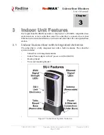
Page 19: ...tation and one or more subscriber units The subscriber is connected to a remote Ethernet network and establishes a bi directional data link with a designated base station 3 1 Indoor Subscriber with Integrated Antenna The subscriber is a fully integrated unit with a built in antenna The subscriber system includes Subscriber with integrated antenna Indoor Power adapter with AC power cord NA UK EU De...

Page 20: ...ption 1 Power on Reset All LEDs are on for a short period 2 Frequency Scanning Walking LED on left to right to left 3 Network Entry The number of LEDs blinking represent the received signal strength Value is from zero all LEDs off to five all LEDs on See table following 4 Subscriber is Registered The number of LEDs on represent the received signal strength Value is from zero all LEDs off to five a...

Page 21: ...ctor 3 3 1 Ethernet Port The auto sensing 10 100Base T Ethernet port connects through the Ethernet cable to the customer network equipment The subscriber exchanges data with the network through this port auto sensing polarity It is recommended to use a flexible Ethernet cable Figure 10 Subscriber Ethernet Connector Under Base 3 3 2 Reset Switch The subscriber features a reset switch recessed in th...

Page 22: ...used for sending receiving the RF signal to from the antenna This port can also be used for connection to an optional external antenna Figure 12 Subscriber RF Connector Under Base 3 3 4 Accessories The subscriber is powered using the supplied auto sensing 110 240 nominal VAC indoor power adapter The power input connection is located on the bottom of the subscriber unit The subscriber includes moun...

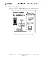
Page 23: ...7 01 01 DRAFT Proprietary Redline Communications 2006 December 13 2006 Page 23 of 60 3 4 Antenna Alignment Refer to the RedMAX Installation Guide P N 70 00079 for detailed installation instructions Figure 14 Subscriber System Connections Diagram ...

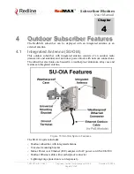
Page 24: ...door subscriber with integrated antenna consists of an outdoor radio transceiver and antenna and an indoor power block with network connections The subscriber electronics are housed in a weatherproof aluminum alloy case and features an integrated antenna Figure 15 SU OIA System Features The SU OIA system includes Outdoor subscriber with integrated antenna Universal mounting bracket Indoor Power ov...

Page 25: ...eatures an RF connector for connection to an external antenna Figure 16 SU ORF System Features The SU ORF system includes Outdoor subscriber with N type RF output Flat plate mounting adapter Indoor Power over Ethernet PoE adapter with AC power cord NA UK EU Outdoor Ethernet cable with weatherproof connector External antenna 40 cm 16 RF cable N type connector 50 Ohm Heavy duty mounting bracket Ligh...

Page 26: ... Ethernet cable is terminated with an environmentally sealed RJ 45 connector for connection to the subscriber The minimum diameter to pass this connector through a conduit or hole is 26 mm 1 in The indoor end of the Redline supplied outdoor hardened CAT 5 Ethernet cable is terminated with a standard indoor RJ 45 connector for connection to the indoor PoE adapter The minimum diameter to pass this c...

Page 27: ...vides two Ethernet interfaces Important Warranty Information PoE Equipment The outdoor subscriber factory warranty is valid only if the Redline supplied Power Over Ethernet PoE power adapter is used Refer to the technical specifications in this manual for a list of Redline approved PoE equipment Figure 19 PoE Connection to DATA POWER OUT Port Table 6 System PoE Ports LED DATA POWER OUT The auto se...

Page 28: ...t on the PoE unit Only the outdoors Ethernet interface cable to the outdoor subscriber can be safely connected to the Data and Power Out connector Table 7 System Ethernet Data Port Link Act LEDs LED Port AC Green Connected Power is active Blink Not connected Output is out of range 4 4 Mounting the Outdoor Subscriber Refer to the RedMAX Installation Guide P N 70 00059 for detailed installation inst...

Page 29: ... bracket can accommodate most 4 45 cm to 11 45 cm 1 4 in OD masts found on many commercial tower installations Figure 21 SU ORF System Connections Diagram 4 4 3 Antenna Alignment The outdoor subscriber includes an audible antenna alignment tool to assist in pointing the antenna for maximum signal strength The signal will sound infrequently when a low signal is detected and more often as the signal...

Page 30: ...or mode provides a dynamic display of the current system statistics updated each few seconds Configuration modes allow you to view and adjust the subscriber network and wireless settings 5 2 1 Telnet Connection Telnet Login Type telnet followed by the IP address of the subscriber system depress ENTER and enter the account and password when prompted The subscriber supports two separate user account...

Page 31: ...le system commands or editing hot keys respectively SUO 5 2 2 Root Commands The following CLI commands are common to all configuration modes Table 9 CLI Root Mode Commands Command Description Use the character as an alternative to typing help ENTER Example Enter the following command string to list all parameters that can be changed using the set command set Exit Return to root mode help Type help...

Page 32: ...lay modify the board parameter configuration bsIdTable Access the Management Base Station ID table diagStatistics Display modify the Diagnostic Status ethTag Display modify the Ethernet Tagging installedVer Display the installed software version s ipAddress Display modify the IP address loadImage Download and run a new software image modThresh Display modify thresholds for adaptive modulation moni...

Page 33: ... around 44000000 RxIfFreq Enter the RxIfFreq Hz value around 44000000 RfType Enter an unsigned char as the new RfType value One of 0 None 1 Radia 3 5 GHz 2 Radia 5 8 GHz 3 SMI 4 Factory Test IfPresent Enter an unsigned char as the new IfPresent value 0 Baseband only 1 IF present TxSpectrumInv Enter a boolean as the new TxSpectrumInv value RxSpectrumInv Enter a boolean as the new RxSpectrumInv valu...

Page 34: ...llowing command string to register a base station ID in table position 7 add 00 11 22 33 44 55 7 Enter delete Delete a base station ID entry The count value will be adjusted to reflect the current number of effective entries If the table position value is not specified the last valid entry in the table is deleted EntryNumber The entry position in the table show Display the base station ID table en...

Page 35: ...easured RSSI value physical layer PhyRssiAvg Average measured RSSI value physical layer RfRssiMin Minimum measured RSSI value radio RfRssiMax Maximum measured RSSI value radio RfRssiAvg Average measured RSSI value radio CableCompMin Minimum cable compensation value used CableCompMax Maximum cable compensation value used CableCompAvg Average cable compensation value used FreqOffsetMin Minimum frequ...

Page 36: ...eneral Uplink General CINR PowerMin 4 1 dBm ModCodeMin 6 ModCodeMin 6 Min 30 5 dB PowerMax 4 1 dBm ModCodeMax 6 ModCodeMax 6 Max 38 3 dB PowerAvg 4 1 dBm ModCodeAvg 6 ModCodeAvg 6 Avg 34 5 dB Sdus 116 Sdus 51 Mpdus 516 Mpdus 68 PHY RF Cable Compensation Frequency Offset RssiMin 16 8 dB RssiMin 49 6 dB CompMin 0 OffsetMin 1 RssiMax 15 8 dB RssiMax 48 6 dB CompMax 0 OffsetMax 4 RssiAvg 16 2 dB RssiA...

Page 37: ...the outermost tag is checked removed The packet is then forwarded to the Ethernet port The following table lists all commands available in this mode Table 14 CLI ethTag Ethernet Tagging Commands Command Description reset Set all parameters to factory default values set Change parameter settings Active Status of the VLAN Tagging feature 0 Inactive will not check or add delete VLAN tags 1 Active wil...

Page 38: ...file from the selected partition 0 Load from partition 0 1 Load from partition 1 show Display the current setting for all parameters Partition 0 MajorNumber Major software release number MinorNumber Minor software release number ReleaseNumber Software release build number Designation Software release designation Partition 1 MajorNumber Major software release number MinorNumber Minor software relea...

Page 39: ...he air secondary management IP address can be assigned only through the base station acting as a DHCP relay agent The DHCP server and a Time of Day ToD server specified in the obtained lease must be located on the network connected to the base station Ethernet port The subscriber can not use any DHCP or ToD server on the network connected directly to the subscriber Ethernet port The DHCP exchange ...

Page 40: ...llowing provides and example update session The subscriber will reboot using the new image automatically following a successful download Example Download Dialog with Subscriber Login admin Password admin welcome to the SS CLI Version 0 3 SUO loadImage Server IP Address enter ftp server IP address here File Name enter binary file name here Opening FTP connection Done Downloading image Done Programm...

Page 41: ...ate1Exit Rate2Exit RW Rate 2 exit threshold Value Rate1Entry Rate2Entry RW Rate 2 entry threshold Value Rate2Exit Rate3Exit RW Rate 3 exit threshold Value Rate2Entry Rate3Entry RW Rate 3 entry threshold Value Rate3Exit Rate4Exit RW Rate 4 exit threshold Value Rate3Entry Rate4Entry RW Rate 4 entry threshold Value Rate4Exit Rate5Exit RW Rate 5 exit threshold Value Rate4Entry Rate5Entry RW Rate 5 ent...

Page 42: ...rcCount DlMapCount DlMapErrCount 311714 0 1 12468 0 DlMapCrcCount UlMapCount UlMapErrCount UlMapCrcCount DcdRxCount 0 311714 0 0 1396 DcdErrCount DcdCrcCount UcdRxCount UcdErrCount UcdCrcCount 0 0 1396 0 0 MgmtRxCount MgmtErrCount MgmtCrcCount LostFrames FrameDuration 87 0 0 1 10000 DcdChangeCount RngTimeCorrection DlByteCount DlSduCount DlMpduCount 0 76 56642560 60824 304083 DlHCrcErrCount DlCrcE...

Page 43: ...id settings are 128 256 512 or 1024 PsDuration Physical slot duration PsPerOFDMSymbol Physical slots per OFDM symbol value in PS SmplFactorNum Above the fraction line in the sampling factor ns Normally set to 8 nsec SmplFactorDen Under the fraction line in the sampling factor ns Normally set to 7 nsec CyclicPrefix Cyclic prefix CP The guard interval is used to factor out multipath effect Valid set...

Page 44: ...itTime Auth Req retransmission interval from Auth Wait state ReauthWaitTime Auth Req retransmission interval from ReauthWait state AuthGraceTime Time prior to Authorization expiration SS begins reauthorization OperationalWaitTime Key Req retransmission interval from Op Wait state RekeyWaitTime Key Req retransmission interval from Re key Wait state TekGraceTime Time prior to TEK expiration SS begin...

Page 45: ... LoRfFreq3 Lower limit of the 3rd Frequency Scan Interval HiRfFreq3 Upper limit of the 3rd Frequency Scan Interval LoRfFreq4 Lower limit of the 4th Frequency Scan Interval HiRfFreq4 Upper limit of the 4th Frequency Scan Interval LoRfFreq5 Lower limit of the 5th Frequency Scan Interval HiRfFreq5 Upper limit of the 5th Frequency Scan Interval LoRfFreq6 Lower limit of the 6th Frequency Scan Interval ...

Page 46: ...le or disable the DHCP relay setting 0 Disable DHCP relay agent 1 Enable DHCP relay agent ethernet Use this setting to modify the Ethernet port auto negotiation link speed and duplex settings AutoNegEnabled value 0 Disabled 1 Enabled LinkSpeed value 0 10M 1 100M LinkDuplex value 0 Half 1 Full managedSS The managedSS command allows you to configure the subscriber for independent operation or enable...

Page 47: ... Disabled Enabled LinkSpeed Link Speed 10 100 LinkDuplex Link Duplex half full eventLog Display the event log messages interfaces Display information about the subscriber wireless and Ethernet interfaces For example ifIndex Desc MAC Address ifAdminStatus ifType ifMtu 1 802 16 00 09 02 00 8c 7f 1 184 2048 2 802 3 00 09 02 00 8c 7f 1 6 1500 sysContact Display the system contact information sysDescri...

Page 48: ...e partitions and run the downloaded file show Display software version information for downloaded binary files Indicates the active version switch Switch to the currently inactive software version Confirmation is required The subscriber will be rebooted This is done automatically following a successful file download sync Synchronize the binary files saved in the active and inactive partitions This...

Page 49: ...pCrcCount Uplink MAP messages with CRC errors UlByteCount Uplink Bytes received UlSduCount Uplink SDUs received from CL UlMpduCount Uplink MPDUs sent MgmtRxCount Total management messages MgmtErrCount Invalid management messages MgmtCrcCount Management messages with CRC errors UcdRxCount Uplink Channel Descriptor messages UcdErrCount Uplink Channel Descriptor messages that are Invalid UcdCrcCount ...

Page 50: ...hannel 2 Up to 35 Mbps Uncoded Rate 7 MHz channel 2 Data Rate Up to 5 Mbps Max Ethernet Rate 3 5 MHz channel 2 Up to 10 Mbps Max Ethernet Rate 7 MHz channel 2 Maximum Tx Power 20 dBm 16 dBm for 64 QAM Rx Sensitivity 93 dBm BPSK 1 2 3 5 MHz channel Cable Maximum length 225 ft 68 m using Redline supplied CAT 5 double shielded outdoor cable without Ethernet lightning protection Network Attributes Tra...

Page 51: ...da RSS 192 RF EN 301 021 EN 301 753 Safety IEC 60950 1 EN 60950 1 UL 60950 1 Operating Temperature Outdoor Unit 40 C to 65 C Antenna Integrated flat panel 14 dBi Optional non integrated 14 5 dBi antenna Wind Loading Antenna 220 Km hr 137 mph Dimensions 20 x 20 x 2 5 cm 8 x 8 x 2 5 in Weight 2 Kg 4 5 lb does not include mounting bracket 1 Frequency range dependant on installed radio option license ...

Page 52: ...ied CAT 5 double shielded outdoor cable without Ethernet lightning protection Network Attributes Transparent bridge 802 1Q VLAN 802 1p DHCP client DHCP pass through Modulation Coding Rates Modulation BPSK QPSK 16 QAM 64 QAM Coding 1 2 2 3 3 4 MAC Cell based PMP deployment 1 CID subscriber 64 subscribers per sector 802 16 2004 compliant PMP 802 16 2004 packet convergence sub layer mode QoS delay CI...

Page 53: ...n Broadcast Ranging Opportunity Timeout This message indicates that the base station has not provided an opportunity for new subscriber registration within the last 10 seconds Classifier deleted Idx nn The specified classifier has been deleted Classifiers deleted for SF with CID XXXX All classifiers have been cleared for the specified service flow DCD Receiving Timeout The subscriber has not recei...

Page 54: ...r SF or CLS rejected SF Id XXXX DSC transaction has been rejected by base station DSC Success SF Id XXXX DSC transaction has been successful DSC DSD Reject SF ID not found base station has requested the deletion of a SFID which does not exist DSD Success SF Id XXXX DSD transaction has successfully completed DSx Action error There has been an error in the creation of a service flow The particular f...

Page 55: ...on Change The MAC has required a reset to apply a configuration change that was made by the user MAC Reset SC Request RES CMD The base station has requested that the subscriber reset its MAC MAC Reset SC Request RES CMD base station has requested that subscriber should reset its MAC MAC Started The MAC processor has been started New Cls for SF with CID XXXX A new classifier has been added to the s...

Page 56: ...on with a base station It will now begin its initial ranging process System startup status The subscriber has begun the bootup sequence The startup status will be included in the text of this message Modes specify a possible reason for reboot TFTP no response T26 nn retries SMC setup has not completed within the allowed time TFTP Completed Successfully This message confirms that SMC registration h...

Page 57: ...g abort telling it to halt the ranging process Uplink Channel Parameters Acquired The subscriber has successfully obtained the uplink channel descriptor Uplink SF nn changed Changes have been successfully applied to the specified uplink service flow Uplink SF nn created CID XXXX No Cls nn An uplink service flow has been successfully created Uplink SF nn not created no space CID XXXX The subscriber...

Page 58: ...n or on the Ethernet port of the subscriber i e laptop b You must copy the binary files into the default file location for the FTP server You can not specify a path in the upgrade dialog c The FTP server must have a user defined as follows username target password secret 6 4 2 Connection to Subscriber If performing the upgrade using the local Ethernet port it is important to use the correct cables...

Page 59: ... target and password secret these settings cannot be altered The image will be uploaded to the subscriber and saved in the non volatile memory flash 3 The subscriber must be reset to load the new software Enter the reboot command to reset the unit The telnet session will be terminated Example Download Dialog with Subscriber Login admin Password admin welcome to the SS CLI Version 0 3 SUO loadImage...

Page 60: ...Doc 70 00057 01 01 DRAFT Proprietary Redline Communications 2006 December 13 2006 Page 60 of 60 302 Town Centre Suite 100 Markham Ontario Canada L3R 0E8 www redlinecommunications com ...

Reviews: