


Inserting and Extracting a MIC
Servicing the Hardware
6-3
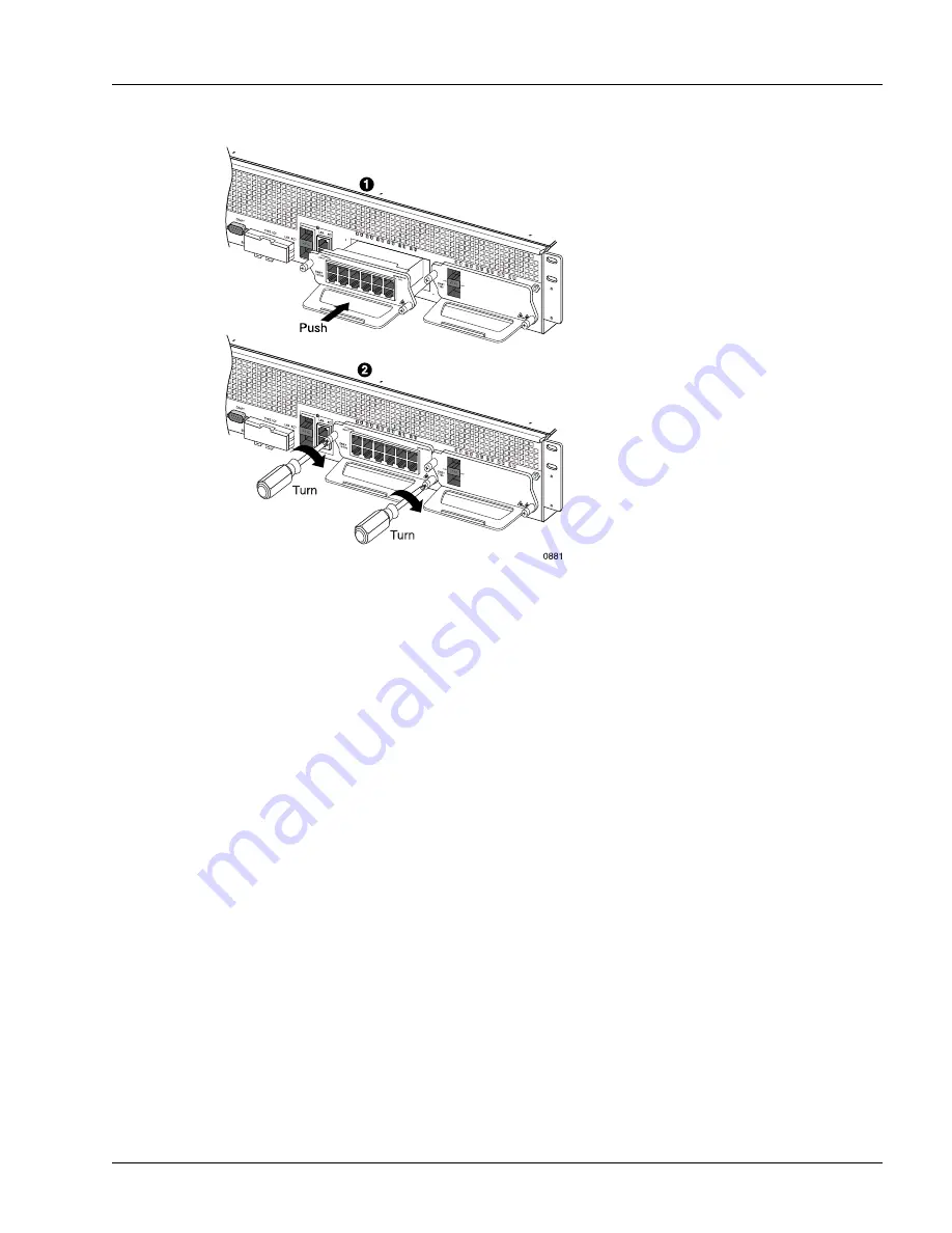
Figure 6-1
Inserting a MIC
Extract a MIC
The following procedure is referenced in the removal procedures for specific MICs; to ensure correct
removal, perform the removal procedure for the specific MIC, including all steps prior to and after the
actual MIC extraction. Perform the following steps to extract a MIC; see Figure 6-2:
1. Put on an antistatic wrist strap (one is shipped with the system), and attach it to an appropriate grounded
surface.
2. Using a Phillips screwdriver, loosen the captive screws on the front panel of the MIC being removed.
3. Holding the MIC handle and keeping it perpendicular to the slot, pull gently on the MIC to disengage
it from the circuit board.
4. Keeping the MIC horizontally level, carefully slide the MIC out of the chassis, and place it in an
antistatic bag.
Note
Do not attach the wrist strap to a painted surface; there is an ESD convenience jack located on
the front of the chassis.
Summary of Contents for SmartEdge 100
Page 4: ......
Page 8: ...viii SmartEdge 100 Router Hardware Guide...
Page 14: ...Ordering Documentation xiv SmartEdge 100 Router Hardware Guide...
Page 52: ...Connecting and Routing the Cables 4 18 SmartEdge 100 Router Hardware Guide...
Page 72: ...Obtaining Assistance 5 20 SmartEdge 100 Router Hardware Guide...
Page 90: ...FE and GE MIC and Native Port Cables A 6 SmartEdge 100 Router Hardware Guide...
Page 94: ...FE and GE Port Alarms B 4 SmartEdge 100 Router Hardware Guide...