CONNECT. MONITOR. CONTROL.
© 2014 Red Lion Controls. All Rights Reserved
1
QUICK START GUIDE
MobilityPro
TM
BT-5600 Series
Verizon Wireless Modem
OVERVIEW
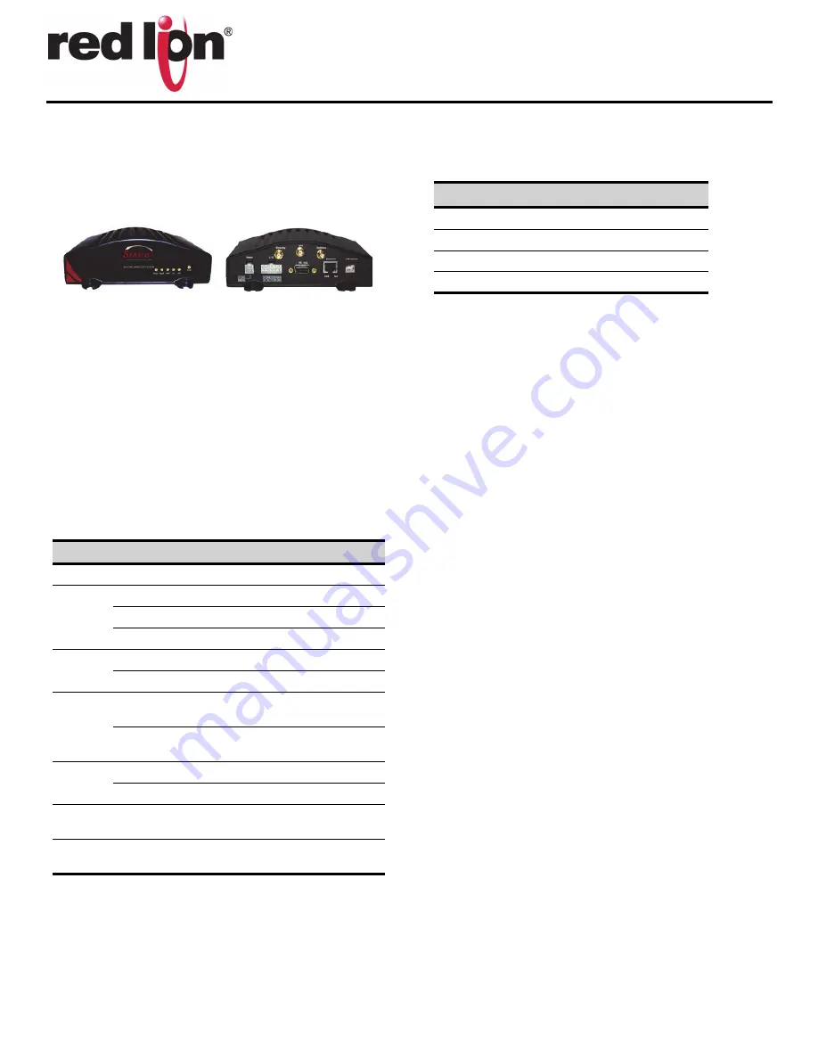
The MobilityPro™ BT-5600 series modems are rugged 3G wireless
modems built to provide simple and reliable communication over the
EVDO Rev. A cellular data network.
This guide covers initial configuration for the BT-5600 & BT-5630.
FEATURES
•
CDMA EVDO Rev. A with fallback to Rev. 0 a, 1XRTT and IS95
•
Diversity antenna
•
Ethernet, Serial, USB and WiFi (5630 model only)
•
Reliable Always-on cellular link
•
Rugged industrial design
•
Remote diagnostics, configuration and updates
•
3 Analog inputs, 4 Digital inputs, 3 Digital outputs
•
IPsec VPN multiple tunnel and 3DES|AES up to 256-bit encryption
LED INDICATORS
ADDITIONAL INFORMATION
Visit our support page at
to access the modem’s docu-
mentation, as well as configuration help, troubleshooting and firmware
& software updates. Or contact Technical Support at 1-877-432-9908 or
.
POWER
The modem has a 4-pin Molex connector for power input and requires
a power source between 8 and 30 VDC.
* An AC-DC power adaptor can be purchased as an accessory.
ANTENNA
An antenna with an SMA connector should be connected to the
modem. This antenna should meet the following specifications:
•
Dual-band 800 & 1900 MHz
•
Nominal 50 ohm impedance
•
Voltage Standing Wave Radio (VSWR) less than 2.5:1
*Antennas are sold separately.
DATA INTERFACES
Ethernet:
10/100 Mbps Auto-sensing Female RJ45 port
USB:
USB 2.0 Type B Female
Serial:
RS-232 9 pin DCE Female, with these default settings:
•
Speed: 115200 bps
•
Data bits: 8
•
Parity: None
•
Stop Bits: 1
•
Flow Control: Hardware
SETUP
1.
Setup a data account for the modem
Contact your Verizon dealer and request a data account to be assigned
to the modem's ESN (electronic serial number). The ESN is printed on
modem's label.
2.
Wiring and power-up
1.
Connect the modem to your computer using a standard Ethernet
cable. Alternatively, the RS-232 or USB ports can be used for
setup.
2.
Connect the cellular antenna to the antenna connector.
3.
Plug in the power connector to power-up the modem.
3.
Start BlueVue Device Manager Software
1.
Download and install the latest version of BlueVue Device Man-
ager from
LED
State
Description
Power
ON
Power is applied to the router
Signal
ON
Excellent signal strength
FLASH
Flashes faster as signal is stronger
OFF
Very weak or no signal (less than -100dBm)
WAN
ON
Wireless link established, but no data activity
FLASH
Data transmitted/received on wireless network
RS232
ON
Link established with serial device but no data
activity
FLASH
Data transmitted/received with attached serial
device
GPS
ON
Position fix available
OFF
No position fix available
Ethernet
Link
ON
Link established with Ethernet device
Ethernet
Activity
FLASH
Data transmitted/received with attached
Ethernet device
LABEL
DESCRIPTION
GND
Ground
POS
Power 8 to 30 VDC (12 or 24 VDC nominal)
IGN
Ignition sense
O3
Digital output


