A-2
INSTALLATION
MEGA FORCE
®
140i MP
®
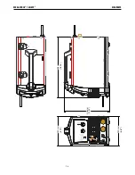
case Front controls
FIGURE A.1
1. Voltage/Amperage Adjustment Knob
– While in WIRE
mode, this knob adjusts the value of the voltage output. While
in TIG or STICK mode, this knob adjusts the value of the
amperage output.
2. Wire Feed Speed Adjustment Knob
– While in WIRE mode,
this knob adjusts the wire feed speed setting. While in TIG or
STICK mode, this knob is inactive.
3. Input/Output Voltage and Temperature LEDs
– The top LED
will illuminate when Input power is present and the machine
is turned on. The middle LED will illuminate when the
machine has thermally tripped. Once the machine has cooled,
the machine will reset and the thermal light will turn off. The
middle LED will flash if the input voltage is above 140 VAC or
below 90 VAC. The middle LED will also flash when power is
removed from the machine. The bottom LED illuminates when
the machine is welding or ready to weld. Safety precautions
must be followed when the machine is welding or ready to
weld. The bottom LED will flash when a short is present.
4. Process Selection Button
– Allows the user to toggle
between processes. The corresponding LED above the button
will indicated the current process.
5. Brass Gun connection
– Permits attachment of a MIG
welding gun, TIG torch or spool gun. Ensure the gun or torch
is fully seated into the brass receptacle and tighten the thumb
screw.
6. Eight Pin Connector
– Permits triggering the machine for
MIG, FCAW, aluminum MIG or TIG welding when a foot pedal
is attached. Also triggers gas flow for MIG, aluminum MIG,
and TIG. Connect the 8-pin connector present on the welding
gun or foot pedal to the receptacle.
7. Wire Drive Polarity Lead
– Permits configuring the wire drive
to positive or negative polarity by inserting into the positive or
negative receptacle. Ensure connector is tightly locked into
place by rotating clockwise.
8. Negative Output Receptacle
– Permits attaching a work
lead, electrode stinger, or the center wire drive polarity lead
to DC negative polarity. Rotate connector clockwise to lock
into place.
9. Positive Output Receptacle
– Permits attaching a work lead,
electrode stinger, or the center wire drive polarity lead to DC
positive polarity. Rotate clockwise to lock into place.
case back controls
FIGURE A.2
1. Power Switch
– Permits turning the machine on or off.
2. Thermal Breaker
– The welding machine features a
resettable 25amp thermal breaker. If the current conducted
through the breaker exceeds 25 amps for an extended period
of time, the breaker will open and require manual reset.
3. Input Power Cord
– Permits the machine to be connected to
120VAC input.
4. Integrated gas solenoid
– permits connecting the proper
shielding gas
1
2
3
8
9
7
6
5
4
1
2
3
4


