REC N-Peak 2 Black Series Installation Manual Download Page 20

20

REC Installation Manual - REC Solar Panels  - IEC 

61215

 /

61730

Rev L 

-


09

.

21


Ref:  PM

-

IM

-20

PANEL MAINTENANCE

CLEANING INSTRUCTIONS

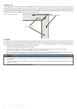
REC solar panels have been designed for easy maintenance. However cleaning solar panels can assist in optimizing electricity output. The need for 

cleaning will vary dependent on location, rainfall, pollution levels and the angle of installation – the lower the angle of installation, the more cleaning 

will be required. ‘Normal’ rainfall will naturally clean the panels if installed at a su

ffi

cient angle to ensure water runs o

ff

 the surface. To optimize 

electrical output it is recommended to clean the panels when dirt can clearly be seen on the glass surface.

Using a so

ft

 rubber squeegee, wipe the panel surface from the top downwards to remove any residual water from the panel glass. Take care not to 

scratch the surface or introduce foreign elements that may cause damage to the panel. Always rinse the panel with plenty of water. Panels can be 

le

ft

 to dry in the air or wiped dry with a clean and so

ft

 cloth or chamois. 

For more information on cleaning REC solar panels, consult the 

REC Cleaning Information Sheet which is available to download from the online REC 

Download Center www.recgroup.com/downloads. If in doubt at any time when cleaning the panels, stop and obtain professional advice.

SYSTEM INSPECTION

The system should be inspected regularly to ensure that: 

•  Fasteners are secure, tight and free from corrosion,
•  Electrical connections are secure, tight, clean and free of corrosion,
•  The mechanical integrity of the cables is intact,
•  Bonding points to ground are tight, secure and free from corrosion (which could break the continuity between the panels and ground).

RECYCLING 

REC makes every e

ff

ort to ensure panel packaging is kept to a minimum. The paper and cardboard packaging can be recycled and the protective 

wrapping and panel separating blocks are also recyclable in many areas. Recycle packaging and panels according to local guidelines and regulations.

DISPOSAL OF OLD ELECTRICAL AND ELECTRONIC EQUIPMENT

Panels should be recycled at the end of their useful life according to local guidelines and regulations. By ensuring REC solar panels are disposed 

of correctly, you will help prevent potential negative impact on the environment and human health. The majority of the panel components can be 

recycled.
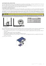
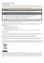
For installations in the European Union, REC solar panels are subject to WEEE regulations. The symbol in fig. 

19

 as found on the label on the rear 

of the panel indicates that this product must not be treated as household waste and must be disposed of at an appropriate collection point for the 

recycling of electrical and electronic equipment. The recycling of the di

ff

erent components and materials will help to conserve natural resources.

Fig. 

19

: WEEE symbol

The European WEEE (Waste Electrical and Electronic Equipment) Directive regulates the correct recycling of electronic and electrical waste in all 

member states of the European Union (EU). For end-customers it is a free of charge disposal system, financed by the manufacturers and importers, 

where panels can be brought to a local recycling depot, or in the case of larger numbers, be picked up from site, as is the case with other electrical 

equipment, e.g., refrigerators or televisions. The extensive process steps for proper disposal are strictly regulated and place no further obligations 

on the owner of the panels. For more information about the recycling of this product, please contact your local recycling authority or recycling 

center.

CAUTION

•  Panel cleaning must always be carried out when the panels are cool, e.g., early morning, to avoid breakage through thermal shock.
•  Use of high pressure hoses or cleaners is not permi

tt

ed as these may damage the panels, laminate or cells.

NOTE

•  Avoid pu

tt

ing pressure on the on the panel surface when cleaning or drying, e.g., leaning, standing or resting buckets on it.

•  Use only deionized water free from grit and physical contaminants, at ambient temperature and use a sponge, microfiber cloth or a so

ft


brush to wipe away the dirt (rainwater, tap water or diluted alcohol may also be used as a secondary solution). 

•  For further cleaning a mild, biological and biodegradable washing-up liquid may be used.
•  If stains require more e

ff

ort to be removed, Isopropyl alcohol of a concentration less than 

10%

 may be used. Acidic or alkaline detergent may 

not be used.

i

Summary of Contents for N-Peak 2 Black Series

Page 1: ...ll REC solar panels certified according to IEC 61215 61730 RECTwinPeak 4 Series RECTwinPeak 4 Black Series REC N Peak Series REC N Peak Black Series REC N Peak 2 Series REC N Peak 2 Black Series REC S...

Page 2: ...ll panels MLPE device installation zones 28 INTRODUCTION 3 SAFETY MEASURES 4 PANEL HANDLING 5 CHOOSING AN INSTALLATION LOCATION 5 ELECTRICAL INSTALLATION 6 MECHANICAL INSTALLATION 6 PANEL INSTALLATION...

Page 3: ...lers are responsible for the following Only qualified personnel must perform work on photovoltaic systems such as installation commissioning maintenance and repairs Be sure to follow the safety instru...

Page 4: ...served during handling to avoid the risk of sparking fire hazards burns and lethal electric shocks Exercise extreme caution when wiring panels and look out for damaged or dirty cables etc Never insert...

Page 5: ...radationtothepackagingorpanelcomponents pallets and panels must be stored in a controlled environment ideally internal where it is protected from the elements e g rain dust and direct sunlight If over...

Page 6: ...ion fault Correct DC polarity must be observed at all times Electrical Ratings ElectricalratingsarewithinaspecifictoleranceofmeasuredvaluesatStandardTestConditions STC asgiveninthetechnicalcharacteris...

Page 7: ...tructions including specific hardware and torque requirements Ensure the clamps used are suitable for the planned installation and expected system design loads The grip area must not extend onto the p...

Page 8: ...00Pa 2400Pa 3600Pa 1600Pa X 622 712 mm 2400Pa 2400Pa 1600Pa 1600Pa 2400Pa 2400Pa 1600Pa 1600Pa 2400Pa 2400Pa 1600Pa 1600Pa X 0 100 mm X 1200Pa 1200Pa 800Pa 800Pa 1600Pa 1600Pa 1066Pa 1066Pa X 100 250...

Page 9: ...learance Gap Clamping zone 20 40 mm 40 60 mm 60 mm 20 mm Test Load DesignLoad Test Load DesignLoad Test Load DesignLoad Test Load DesignLoad 0 650 mm 1200Pa 1200Pa 800Pa 800Pa 3000Pa 2400Pa 2400Pa 160...

Page 10: ...600Pa 1600Pa X 0 100 mm X 1200Pa 1200Pa 800Pa 800Pa 1600Pa 1600Pa 1066Pa 1066Pa X 100 250 mm X 800Pa 800Pa 533Pa 533Pa 2400Pa 2400Pa 1600Pa 1600Pa X Rail length under module 100 200 mm Min 100 mm Max...

Page 11: ...Pa 2800Pa 1600Pa 5400Pa 2400Pa 3600Pa 1600Pa X 340 420 mm 1800Pa 1800Pa 1200Pa 1200Pa 6200Pa 4000Pa 4133Pa 2666Pa 7000Pa 4000Pa 4666Pa 2666Pa X 420 520 mm 1200Pa 1200Pa 800Pa 800Pa 3000Pa 2400Pa 2400P...

Page 12: ...m 4 in 250 mm 9 8 in 250 mm 9 8 in 100 mm 4 in 100 mm 4 in 650 mm 25 6 in 0 0 0 0 0 0 650 mm 25 6 in Rail position Rail position Legend Clearance Gap Clamping zone 20 40 mm 40 60 mm 60 mm 20 mm Test L...

Page 13: ...Pa 1600Pa X 0 100 mm X 1200Pa 1200Pa 800Pa 800Pa 1600Pa 1600Pa 1066Pa 1066Pa X 100 250 mm X 800Pa 800Pa 533Pa 533Pa 2400Pa 2400Pa 1600Pa 1600Pa X Rail length under module 100 200 mm Min 100 mm Max 200...

Page 14: ...0Pa 1600Pa X 225 357 mm 1800Pa 1800Pa 1200Pa 1200Pa 4200Pa 2400Pa 2800Pa 1600Pa 5400Pa 2400Pa 3600Pa 1600Pa X 357 582 mm 1800Pa 1800Pa 1200Pa 1200Pa 6200Pa 4000Pa 4133Pa 2666Pa 7000Pa 4000Pa 4666Pa 26...

Page 15: ...ELS WITH CONTINOUS RAILS PARALLEL TO LONG SIDE OF THE PANEL A continous rail or other support structure spans the complete underside of the panel Legend Clearance Gap Clamping zone 20 40 mm 40 60 mm 6...

Page 16: ...357 582 mm 1200Pa 1200Pa 800Pa 800Pa 3000Pa 3000Pa 2000Pa 2000Pa 4200Pa 4000Pa 2800Pa 2666Pa X 582 622 mm 1200Pa 1200Pa 800Pa 800Pa 2400Pa 2400Pa 1600Pa 1600Pa 3600Pa 2400Pa 2400Pa 1600Pa X 622 712 mm...

Page 17: ...s apply a safety factor of 1 5 to the stated test load e g test load 5400 Pa 1 5 3600 Pa design load Part Name Material Rail 6105 T5 aluminum extrusion Bolt M6 x 25 drop inT stud kit Nut M6 flanged he...

Page 18: ...d the short side as shown in fig 16 and can be further identified by the grounding symbol stamped in the frame next to it Check all applicable requirements before beginning installation Suitable groun...

Page 19: ...lestandards e g IEC 62852orUL6703 toensuretheyarefitforpurposeandsafety Useofanychemicalsorlubricantsontheconnectorsorcontactsmayonlybecarriedoutinlinewiththeconnectormanufacturer sinstructions TheREC...

Page 20: ...to local guidelines and regulations By ensuring REC solar panels are disposed of correctly you will help prevent potential negative impact on the environment and human health The majority of the panel...

Page 21: ...3 34 7 35 0 NominalPowerCurrent IMPP A 10 62 10 65 10 68 10 72 OpenCircuitVoltage VOC V 40 6 40 8 41 0 41 2 ShortCircuitCurrent ISC A 11 26 11 32 11 38 11 45 PanelEfficiency 19 7 20 0 20 3 20 5 Values...

Page 22: ...34 3 34 7 NominalPowerCurrent IMPP A 10 60 10 62 10 65 10 68 OpenCircuitVoltage VOC V 40 5 40 6 40 8 41 0 ShortCircuitCurrent ISC A 11 19 11 26 11 32 11 38 PanelEfficiency 19 4 19 7 20 0 20 3 Values...

Page 23: ...ncy 18 3 18 6 18 9 19 2 19 5 19 8 Values at standard test conditions STC air mass AM 1 5 irradiance 1000 W m temperature 25 C based on a production spread with a toleranceofPMAX VOC ISC 3 withinonewat...

Page 24: ...10 28 PanelEfficiency 18 3 18 6 18 9 19 2 19 5 Values at standard test conditions STC air mass AM 1 5 irradiance 1000 W m temperature 25 C based on a production spread with a toleranceofPMAX VOC ISC 3...

Page 25: ...ominalPowerCurrent IMPP A 10 62 10 65 10 68 10 72 OpenCircuitVoltage VOC V 40 8 40 9 41 1 41 3 ShortCircuitCurrent ISC A 11 31 11 36 11 41 11 46 PanelEfficiency 19 7 20 0 20 3 20 5 Values at standard...

Page 26: ...VMPP V 33 5 33 9 34 3 34 7 NominalPowerCurrent IMPP A 10 60 10 62 10 65 10 68 OpenCircuitVoltage VOC V 40 7 40 8 40 9 41 1 ShortCircuitCurrent ISC A 11 27 11 31 11 36 11 41 PanelEfficiency 19 4 19 7...

Page 27: ...slack to prevent damage due to water level changes and wave motions ii Mounting panels Installation of REC solar panels must be in accordance with the aforementioned standard mounting instructions Th...

Page 28: ...MLPE devices may also be attached to the mounting construction In such cases refer to the instructions provided by the manufacturer Wherever possible the installation of the MLPE device should not co...

Page 29: ...he market of electrical equipment designed for use within certain voltage limits The technical documentation and full compliance with the standards listed below proves the conformity of the product wi...

Page 30: ...08 2019 E Updated Datasheets 01 2020 F Updated Datasheets 06 2020 G Updated Installation Manual Layout removed REC Peak Energy Series inclusion of REC N Peak Series 09 2020 H Addition of REC TwinPeak...

Page 31: ...RECSOLARPTE LTD 20TUASSOUTHAVENUE14 SINGAPORE637312 SINGAPORE Tel 6564959228 Mail post recgroup com www recgroup com...

Reviews: